- 商品
- 详情
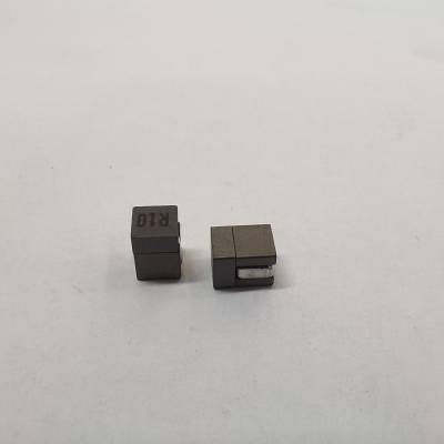
H-EAST替代组合式贴片低感值芯片显卡服务器主板电感59PR9872N
- ¥1.70 ≥1PCS起批
- h-east品牌
- 保护应用范围
- 固定电感种类

Size:10x5.4x7.5~10.5x6.4x9.5mmInductance :0.2~0.25uHI-Sat:~55A特点:1. 大电流2. DCR低3. 屏蔽结构4. 低损耗铁氧体材料应用:降压/升压电压调节器设计。大电流、高频、VRM设计。服务器、台式机、PDA、图形卡、笔记本电脑、电信交换机和路由器。
Size:8x6x8mm~10x7x9.2mmInductance :0.1~0.3uHI-Sat:~100A
特点:1. 低损耗铁氧体材质2. DCR低3. 屏蔽结构4. 可自动化生产应用:多相和V core调节器,电压调节器模块(VRM)和高功率密度VRM服务器,桌面中央处理器(CPU),双数据速率同步动态随机存取存储器(DDR),开关电源输出扼流圈
Size:4x4x4~13x13x9mmInductance : <0.5uHI-Sat:~60A特点:1. 大电流,低损耗2. DCR低3. 屏蔽结构4. 低损耗铁氧体材料应用:服务器,桌面VRMs,EVRD,V core, DDR等大电流区域组成部件:SI2E SeriesSMD Power Bead特点:1. 大电流,低铁损2. DCR低3. 屏蔽结构4. 频率范围高达2 MHz应用:多相和Vcore,调节器电压调节器模块(VRM),服务器和台式VRM,笔记本调节器数据网络,存储系统图形卡和电池电源系统负载模块点.
Size:9.7x4.7x9.7mm~15.5x11.5x14.7mmInductance :0.1~0.5uHI-Sat:~100A特点:1. 大电流,低铁损2. DCR低3. 屏蔽结构4. 频率范围高达2 MHz应用:多相和Vcore,调节器电压调节器模块(VRM),服务器和台式VRM,笔记本调节器数据网络,存储系统图形卡和电池电源系统负载模块点
类型二:大功率组合式电感适用于电源开关、个人计算机、工业计算机和其他大电流直流输出设计, 一般使用VRM Choke或CPU Choke命名,俗称大功率组合电感。
Size:8x8x6~13.5x12.5x10mmInductance :0.3~4.7uHI-Sat:~50A特点:1. 屏蔽结构2. 复合结构,选材灵活3. 可增减圈数调整感量4. 可自动化生产应用:适用于电源线DC-DC转换应用,尤其适用于电源开关、个人计算机、工业计算机和其他大电流直流输出设计。
Size:8x8x6~13.5x12.5x10mmInductance :0.3~4.7uHI-Sat:~50A特点:1. 屏蔽结构2. 低损耗铁氧体材料3. 可增减圈数调整感量应用:适用于电源线DC-DC转换应用,尤其适用于电源开关、个人计算机、工业计算机和其他大电流直流输出设计
类型三:PFC CHOKEATX电源,工控机电源,开放式框架电源,服务器电源,大功率DC-DC变换器应用,一般以PFCCHOKE命名
Size:18x10x15.7~37x19x27mmInductance :0.5~10uHI-Sat:~100A特点:1. 复合材料(铁氧体+Sendust)可降低磁饱和,屏蔽结构2. 的EMC性能3. 较低的DCR值应用:ATX电源,工控机电源,开放式框架电源,服务器电源,大功率DC-DC变换器
ELECTRICAL CHARACTERISTICS @ 25oC (unless otherwise noted)AF4263SUGGESTED PCB LAYOUTDrawing NOT to scale0.160[4,06](2 PL.)120.100[2,54]0.140[3,56]Part Number59PR987xNxxxxS0.433 [11,00]MAX0.283 [7,20]MAX210.300 [7,62]0.005 [0,13]2 PLS0.100 +/- 0.02[2,54 +/- 0,51]2 PLSDim. A0.061 [1.55]Add an "R" to the part number after "P" for the RoHS compliant version (i.e. 59PR9871N is the RoHS compliant version of 59P9871N).Trise (oC) = Core Loss + DCR LossTRF A0.833DCR Loss (mW) = Idc2+… I22x TYP DCR (mOhms)Core Loss (mW) = TRF B x (F)1.84x (TRF C x … I)2.28IDC = DC output current (ADC)… I = Delta I across the inductor (Amps)F = Switching frequency (kHz)The Saturation Current (Isat) is the current at which the Inductance dropsby a maximum of 20% below the lower limit of its value specified at 0 ADCBias. Inductance at Isat is measured at the specified Ambient Temperatureby applying DC Bias by a short period of time to minimize the self-heatingeffect of the component.The Temperature Rise Current is the current at which the temperature ofthe part increases by 50oC. This test is performed with the part mounted ona PCB with traces having 1.7 times the cross sectional area of the copperleads of the part. The temperature of the part is measured after applyingthe DC current for a minimum of 10 minutes.Inductance is measured at 100 KHz and 1.0 Vrms.Temperature Rise can be estimated using the following formulas:1.2.3.4.59P9870N59P9871N59P9872N59P9873N59P9874N59P9875N59P9876N0.307 [7.80]0.299 [7.60]P/N MAXDimension A0.299 [7.60]0.295 [7.50]0.295 [7.50]0.295 [7.50]0.295 [7.50]± 15%Inductance3@ 0 Adc220300400510120150nH70Inductance3@ Isat1(25oC)MINnH1502042723478210248Isat1(Max Saturation Current)ADC25oC 100oC 125oC392919147358116413020157660120473423178770138Temp. RiseCurrent2MAXADC48484848484848Temp. RiseFactor A(TRF A)4Temp. RiseFactor B(TRF B)4Temp. RiseFactor C(TRF C)46.106.106.106.106.106.106.100.0042230.0042030.0041910.0041830.0042960.0042650.0044280.043340.059140.078870.100570.023570.029500.01364DCRmOhms0.290.290.290.290.290.290.29± 10%RoHS59PR9873N59PR9874N59PR9875N59PR9876N59PR9872N59PR9871N59PR9870N59P9873N59P9874N59P9875N59P9876N59P9872N59P9871NClassic59P9870N
 在线问
在线问
- h-east
- 保护
- 固定电感
- 59PR9872N
- 单层间绕式
- 铁氧体磁芯
- 工字形
- 高频
- 卧式非密封
- 胶木
- 8.2uh
- 0.1%
- 24.80&Omega,
- 280mA
- 12F
- 220V
- 网络通信
- 电感器
- 贴片电感
- 800
- 1234
