产品介绍Product introduction
典型为3.2瓦。
信号
每个键相器模块接受:
最多两个传感器信号来自
接近探头传感器或
磁性拾取器。输入
信号范围为+0.8 V至-21.0 V
(非隔离输入/输出模块)或+5V
至-11V(隔离输入/输出模块)。
超过此范围的信号包括:
由模块内部限制。
无源磁性拾取器需要:
轴的旋转速度更大
大于200rpm(3.3Hz)。
输入
阻抗
21.8 k ***限度
信号调节
速度/
频率
信号范围
输入范围为1至1200000 cpm
(0.017至20kHz)。支持
每转多个事件
20 kHz。
输出范围为1至99999 cpm
(0.017至1667赫兹)
速度/
频率
信号精度
***为+25丙(升77)F) 。
未加工
信号
0.017到100赫兹…每分钟1次
101到500赫兹…8 cpm
501到20千赫…cpm的1%
处理
信号
0.017到60赫兹…每分钟1次
61到150赫兹…8 cpm
151至20千赫…cpm的1%
传感器调节
自动阈值
最小信号幅度
触发为2伏峰间电压
最小频率为120
转速(2赫兹)。
手册
门槛
用于0.017 Hz以上的任何输入
(1个事件/转的转速为1 rpm)。
用户可从0到-20选择
直流电压。最小信号
触发幅度为500
毫伏峰间电压。
迟滞
用户可从0.2到2.5选择
伏特。
输出
缓冲
键相器
信号
两个缓冲键相器输出
可在
机架通过同轴连接器。二
缓冲键相器输出为:
也可在
机架通过欧式连接器。
输出
阻抗
504 缓冲输出
阻抗。
键相器
传感器
电源
-24 Vdc,403.2 Watts typical.
Signal
Each Keyphasor Module accepts
up to two transducer signals from
proximity probe transducers or
magnetic pickups. The input
signal range is +0.8 V to -21.0 V
(Non-***lated I/O modules) or +5V
to -11V (***lated I/O modules).
Signals exceeding this range are
limited internally by the module.
Passive magnetic pickups require
a shaft rotative speed greater
than 200 rpm (3.3 Hz).
Input
Impedance
21.8 k minimum.
Signal Conditioning
Speed/
Frequency
Signal Ranges
Input range of 1 to 1,200,000 cpm
(0.017 to 20 kHz). Supports
multiple events per revolution to a
maximum of 20 kHz.
Output range of 1 to 99,999 cpm
(0.017 to 1667 Hz)
Speed/
Frequency
Signal Accuracy
Specified at +25 C (+77 F).
Non-processed
Signals
0.017 to 100 Hz … 1 cpm
101 to 500 Hz … 8 cpm
501 to 20 kHz … 1% of cpm
Processed
Signals
0.017 to 60 Hz … 1 cpm
61 to 150 Hz … 8 cpm
151 to 20 kHz … 1% of cpm
Transducer Conditioning
Auto Threshold
Minimum signal amplitude for
triggering is 2 volts peak to peak
and minimum frequency is 120
rpm (2 Hz).
Manual
Threshold
Use for any input above 0.017 Hz
(1 rpm for 1 event/revolution).
User-selectable from 0 to -20
volts dc. Minimum signal
amplitude for triggering is 500
millivolts peak to peak.
Hysteresis
User-selectable from 0.2 to 2.5
Volts.
Outputs
Buffered
Keyphasor
Signals
Two buffered Keyphasor outputs
are available at the front of the
rack via coaxial connectors. Two
buffered Keyphasor outputs are
also available at the back of the
rack via Euro Style connectors.
Output
Impedance
504 maximum buffered output
impedance.
Keyphasor
Transducer
Power Supply
-24 Vdc, 40
产品信息产品类别:模块卡件
品牌:DCS、PLC
电话:15270269218
联系人:叶经理
质保期:1年
加工定制:不可定制
产地/厂家:美国

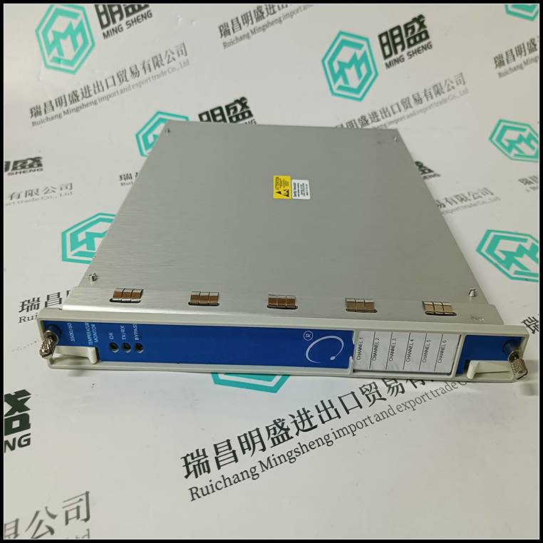
产品实拍图Product picture
DIN导轨凹槽
快速释放夹
设备说明
33003411 07/2007 39
复位按钮
概述该设备配有复位按钮。如果电脑:
连接密码丢失。
使用重置
按钮
您可以通过上方的一个小圆形开口访问该按钮
外壳,距左边缘约40…50毫米(1.57…1.97英寸)。
仅在重新启动设备时使用此按钮,并将此按钮保持在按下状态
至少20秒。在设备运行时按下复位按钮不会产生任何结果。
按下重置按钮时生效,
�停用所有帐户(默认管理员帐户除外
无密码)和
� IP地址和系统ID(SRS)设置为默认值。
注意:激活重置按钮后,值将被修改并保持有效
直到下次重新启动。下次重新启动后,将恢复以前的值。你
如有必要,可以输入新信息。
设备说明
40 33003411 07/2007
表达
安全PLC anIEC 62061概述,以及
VDI/VDE 2180***至4页,在安全相关系统的情况下
公司必须安排验证测试。
周期证明
测试
可通过执行全安全回路对模块进行验证测试。
实际上,输入和输出现场设备具有更频繁的验证测试间隔
例如每6个月或12个月)。如果最终用户测试完成
安全回路:由于现场设备,模块自动包括在内
在这些测试中。模块不需要额外的定期测试。
如果现场设备的验证测试不包括模块,则PES需要:
至少每10年测试一次。这可以通过执行重置来完成
模块的。
如果特定模块有定期验证测试要求,则最终用户应通过以下方式参考这些模块的数据表:
�使用在线测试功能-它可以监控信号值和
当系统执行程序时,逻辑计划中的变量。
�使用显示CPU、COM和
I/O模块。
短路条件
输出电路端子不得与连接的负载连接。万一
导致的高电流可能会损坏端子。
不遵守这些说明可能导致死亡、重伤或
设备损坏。
警告
应用和功能
32 33003411 07/2007
更换故障
模块
如果安全远程输出设备出现故障,则使用以下更换程序:
测试
输入和
输出
干扰
电压和
接地故障
不允许的干扰电压可以用万能测试仪测量。我们
建议测试每个端子是否存在未经批准的干扰电压。
测试外部电缆的绝缘电阻、短路和线路时
断开,电缆两端不得连接,以防止出现缺陷或
过电压导致XPSMF2DO1602损坏。
在将现场电缆连接到设备之前,应测试接地故障。这个
必须断开传感器的供电电压,以及
负极和致动器。如果负极在运行期间接地,则
测试接地故障时,必须断开接地连接。这也是
适用于现有接地故障测试仪的接地连接。每个终端都可以
只能使用电阻测试仪或类似测试仪器进行接地测试。
允许测试一根或多根导线对地绝缘,但不能测试两根
静音电线。也不允许进行高压测试。
测量电路电压和绝缘电阻的指南可在中找到
EN 50178。
步进动作
1断开特定模块的电源。
2断开所有端子(不需要拆卸输入或输出导线)。
3从远程输出模块断开通信-以太网。
4松开DIN导轨夹并卸下模块。
5安装新模块并松开DIN导轨夹。
6重新连接电源。
7通过以太网电缆连接到正在执行XPSMFWIN的PC。
8为MAC地址和IP地址输入新的通信设置。
9下载上一模块使用的配置。
10将所有输出端子连接到新模块。无需重新布线,但
必须检查端子,以确保其处于良好的工作状态。
11重新建立网络连接。
12运行模块。DIN rail recess
Quick release clip
Equipment Description
33003411 07/2007 39
Reset Button
Overview The device is equipped with a Reset button. The Reset button is used if the PC
connection password is lost.
Using Reset
Button
You can access the pushbutton through a small round opening on the upper side of
the housing, about 40...50 mm (1.57...1.97 in.) from the left rim.
Use the button only while you reboot the device and keep the button pressed for at
least 20 s. Pushing the Reset button while the device is running produces no result.
Effect When you push the Reset button,
� all accounts are deactivated (except the default Administrator account
without password) and
� IP addresses and system ID (SRS) are set to default values.
Note: After activation of the Reset button, values are modified and remain valid
until the next reboot. After the next reboot the previous values are restored. You
can enter new information, if necessary.
Equipment Description
40 33003411 07/2007
Communication
Overview The Safety PLCs anIEC 62061, and
VDI/VDE 2180 sheet 1 to 4, in case of safety-related systems the operating
company has to arrange for proof tests.
Periodic Proof
Testing
The modules can be proof tested by executing the full safety loop.
In practice the input and output field devices have a more frequent proof test interval
(e.g., every 6 or 12 months) than the modules. If the end-user tests the complete
safety loop because of the field devices then the modules are automatically included
in these tests. No additional periodic tests are required for the modules.
If the proof test of the field devices does not include the modules then the PES needs
to be tested as a minimum once in 10 year. This can be done by executing a reset
of the modules.
In case there are periodic proof test requirements for specific modules then the enduser should refer to the data sheets of these modules ways:
� Using the On-line test function - it can monitor the values of the signals and
variables within the logic plan, while the systems are executing the program.
� Using the Diagnostics window that displays all states of the CPU, COM, and
I/O modules.
SHORT-CIRCUIT CONDITION
The output circuit terminals must not be connected with the connected load. In case
of a short-circuit, the resulting high current may damage the terminals.
Failure to follow these instructions can result in death, serious injury, or
equipment damage.
WARNING
Application and Function
32 33003411 07/2007
Replacing Faulty
Modules
If a safety remote output device fails, the following replacement procedure is used:
Testing the
Inputs and
Outputs for
Interference
Voltage and
Earth Faults
Inadmissible interference voltage can be measured with a universal tester. We
recommend testing every single terminal for unapproved interference voltage.
When testing the external cables for insulation resistance, short-circuit, and line
break, the cables must not be connected at both ends to prevent defects or
destruction of the XPSMF2DO1602 caused by excessive voltages.
Earth faults are to be tested before connecting the field cable to the devices. The
feed voltage must be disconnected from the sensors, as well as between the
negative pole and the actuators. If the negative pole is earthed during operation, the
earth connection must be disconnected while testing for earth faults. This also
applies to the earth connection of an existing earth fault tester. Every terminal can
only be tested against earth with a resistance tester or a similar test instrument.
Testing the insulation of one or more wires against earth is admissible, but not two
muted wires. High voltage testing is also not admissible.
Guidelines to measure circuit voltage and insulation resistance can be found in
EN 50178.
Step Action
1 Disconnect power supply to the specific module.
2 Disconnect all terminals (removing input or output wires is not required).
3 Disconnect communication - Ethernet from the remote output module.
4 Loosen the DIN rail clip and dismount the module.
5 Mount the new module and release the DIN rail clip.
6 Re-connect power supply.
7 Connect to the PC that is executing XPSMFWIN via Ethernet cable.
8 Enter new communication settings for MAC address and IP address.
9 Download the configuration used by the previous module.
10 Connect all output terminals to the new module. Rewiring is not necessary, but
the terminals must be inspected to ensure they are in good operating condition.
11 Re-establish network connection.
12 Run the module.