产品介绍Product introduction

产品信息产品类别:模块卡件
品牌:DCS、PLC
电话:15270269218
联系人:叶经理
质保期:1年
加工定制:不可定制
产地/厂家:美国
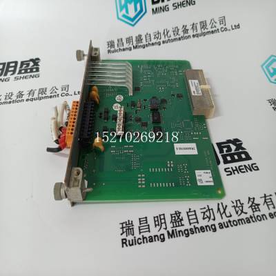
产品实拍图Product picture
•高优先级如果发生高优先级报警,显示器会通知
您有两种方式:显示屏上的LED背光闪烁,直到您
确认报警,报警时报警图标闪烁
是活动的。
•中等优先级如果发生中等优先级报警,则报警
图标仅在报警激活时闪烁。一旦报警
变为非活动状态,报警图标停止闪烁并保持打开状态
显示器。
•低优先级如果发生低优先级报警,报警图标闪烁
仅当警报激活时。一旦警报变为无效,
报警图标从显示器上消失。
•无优先级如果报警设置为无优先级,则不可见
表示将出现在显示器上。无优先级报警
未输入报警日志。参见第8章-记录
报警记录信息。
如果具有不同优先级的多个警报同时激活,
显示屏显示上次发生报警的报警消息。
有关从功率表显示器设置警报的说明,
参见第23页的“设置报警”。
查看报警活动和历史记录
1.按##:直到报警可见。
2.按闹钟。
3.查看电源上列出的激活报警
仪表显示。如果没有活动警报,
屏幕显示“无活动报警”
4.如果有激活的报警,按
<--或-->查看不同的报警。
5.按历史。
6.按<--或-->查看不同的
警报的历史。
7.按1;返回摘要
屏幕
���
�&#39;� �&#39;��
�� �
���
�� ��
;
"2=
�K�5�
���
��
PLSD110258
©2006施耐德电气。版权所有。
PowerLogic®800系列功率表63230-500-22***1
第6章-基本报警6/2006
78
设***控制功能的类型
本节介绍了一些常见的报警功能
以下信息适用:
•太大而无法装入显示器的值可能需要缩放
因素。有关比例因子的更多信息,请参阅“更改
比例因子”,见第219页。
•继电器可配置为正常、锁定或定时。看见
第5章第64页“继电器输出操作模式”-
更多信息的输入/输出功能。
•当警报发生时,功率表运行任何规定
继电器。有两种方法可以释放处于锁定状态的继电器
模式:
-发出命令使继电器断电。见附录B-
有关使用的说明,请使用命令界面
命令接口,或
-确认高优先级日志中的警报以释放
继电器处于锁存模式。从显示器的主菜单,
按报警查看并确认未确认
警报。
下面的列表显示了一些可用的报警类型
常见报警功能:
注:基于电压的报警设定值取决于您的系统
配置三线制系统的报警设定值为VL-L值
而4线系统是VL-N值。
欠电压:以伏特为单位输入拾取和下降设***。
每相欠压报警发生在每相
电压等于或低于拾取设***的时间足以满足
***的拾取延迟(秒)。欠压报警
当相电压保持在下降设***以上时清除
对于***的退出延迟时间段。
过电压:以伏特为单位输入拾取和下降设***。这个
当每相电压为
等于或高于拾取设***,足够长以满足
***的拾取延迟(秒)。过电压报警清除
当相电压保持低于
***的退出延迟时间。
不平衡电流:输入拾取和下降设***
***之零点,基于每个
©2006施耐德电气。版权所有。
63230-500-22***1 PowerLogic®800系列功率表
6/2006第6章-基本报警
79
相电流相对于所有相电流的平均值。对于
例如,输入7%的不平衡量作为70。不平衡电流
当相电流偏离平均值时发生报警
相电流,按***比拾取设***,用于
***的拾取延迟。当***比
相电流与所有相平均值之差
对于***的下降延迟,保持低于下降设定值
时期
不平衡电压:拾取和下降设***输入
***之零点,基于每个
相电压相对于所有相电压的平均值。对于
例如,输入7%的不平衡量作为70。不平衡电压
当相电压偏离平均值
相电压,按***比拾取设***,用于
***的拾取延迟。当***比
相电压与所有相平均值之间的差值
在规定的下降延迟(in
秒)。
相位损耗电流:拾取和下降设***输入
安培。缺相电流报警发生
• High priority—if a high priority alarm occurs, the display informs
you in two ways: the LED backlight on the display flashes until you
acknowledge the alarm and the alarm icon blinks while the alarm
is active.
• Medium priority—if a medium priority alarm occurs, the alarm
icon blinks only while the alarm is active. Once the alarm
becomes inactive, the alarm icon stops blinking and remains on
the display.
• Low priority—if a low priority alarm occurs, the alarm icon blinks
only while the alarm is active. Once the alarm becomes inactive,
the alarm icon disappears from the display.
• No priority—if an alarm is setup with no priority, no visible
representation will appear on the display. Alarms with no priority
are not entered in the Alarm Log. See Chapter 8—Logging for
alarm logging information.
If multiple alarms with different priorities are active at the same time,
the display shows the alarm message for the last alarm that occurred.
For instructions on setting up alarms from the power meter display,
see “Set Up Alarms” on page 23.
Viewing Alarm Activity and History
1. Press ###: until ALARM is visible.
2. Press ALARM.
3. View the active alarm listed on the power
meter display. If there are no active alarms,
the screen reads, “NO ACTIVE ALARMS.”
4. If there are active alarms, press
<--or --> to view a different alarm.
5. Press HIST.
6. Press <-- or --> to view a different
alarm’s history.
7. Press 1; to return to the SUMMARY
screen.
���
�&#39;� �&#39;��
��H ��� &#39;
�� �
���
�� ��
;
"2=
�K�5�
���
��
PLSD110258
© 2006 Schneider Electric. All Rights Reserved.
PowerLogic® Series 800 Power Meter 63230-500-22***1
Chapter 6—Basic Alarms 6/2006
78
Types of Setpoint-controlled Functions
This section describes some common alarm functions to which the
following information applies:
• Values that are too large to fit into the display may require scale
factors. For more information on scale factors, refer to “Changing
Scale Factors” on page 219.
• Relays can be configured as normal, latched, or timed. See
“Relay Output Operating Modes” on page 64 in Chapter 5—
Input/Output Capabilities for more information.
• When the alarm occurs, the power meter operates any specified
relays. There are two ways to release relays that are in latched
mode:
— Issue a command to de-energize a relay. See Appendix B—
Using the Command Interface for instructions on using the
command interface, or
— Acknowledge the alarm in the high priority log to release the
relays from latched mode. From the main menu of the display,
press ALARM to view and acknowledge unacknowledged
alarms.
The list that follows shows the types of alarms available for some
common alarm functions:
NOTE: Voltage based alarm setpoints depend on your system
configuration. Alarm setpoints for 3-wire systems are VL-L values
while 4-wire systems are VL-N values.
Undervoltage: Pickup and dropout setpoints are entered in volts.
The per-phase undervoltage alarm occurs when the per-phase
voltage is equal to or below the pickup setpoint long enough to satisfy
the specified pickup delay (in seconds). The undervoltage alarm
clears when the phase voltage remains above the dropout setpoint
for the specified dropout delay period.
Overvoltage: Pickup and dropout setpoints are entered in volts. The
per-phase overvoltage alarm occurs when the per-phase voltage is
equal to or above the pickup setpoint long enough to satisfy the
specified pickup delay (in seconds). The overvoltage alarm clears
when the phase voltage remains below the dropout setpoint for the
specified dropout delay period.
Unbalance Current: Pickup and dropout setpoints are entered in
tenths of percent, based on the percentage difference between each
© 2006 Schneider Electric. All Rights Reserved.
63230-500-22***1 PowerLogic® Series 800 Power Meter
6/2006 Chapter 6—Basic Alarms
79
phase current with respect to the average of all phase currents. For
example, enter an unbalance of 7% as 70. The unbalance current
alarm occurs when the phase current deviates from the average of
the phase currents, by the percentage pickup setpoint, for the
specified pickup delay. The alarm clears when the percentage
difference between the phase current and the average of all phases
remains below the dropout setpoint for the specified dropout delay
period.
Unbalance Voltage: Pickup and dropout setpoints are entered in
tenths of percent, based on the percentage difference between each
phase voltage with respect to the average of all phase voltages. For
example, enter an unbalance of 7% as 70. The unbalance voltage
alarm occurs when the phase voltage deviates from the average of
the phase voltages, by the percentage pickup setpoint, for the
specified pickup delay. The alarm clears when the percentage
difference between the phase voltage and the average of all phases
remains below the dropout setpoint for the specified dropout delay (in
seconds).
Phase Loss—Current: Pickup and dropout setpoints are entered in
amperes. The phase loss current alarm occurs when any current
value (but not all current values) is equal to or below the pickup
setpoint for the specified pickup delay (in seconds). The alarm clears
when one of the following is true:
• All of the phases remain above
 DSQC230工控继电模块PLC库存
¥6973.00
 DSQC233工控继电模块PLC库存
¥6973.00
 DSQC235A工控继电模块PLC库存
¥6973.00
 DSQC235B工控继电模块PLC库存
¥6973.00
 DSQC236A工控继电模块PLC库存
¥6973.00
 DSQC236B工控继电模块PLC库存
¥6973.00


