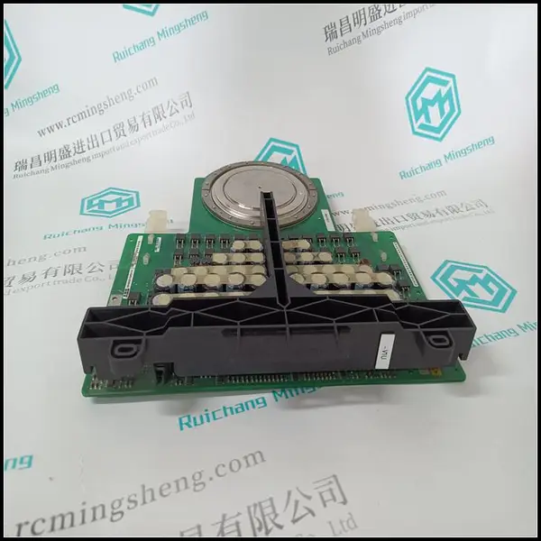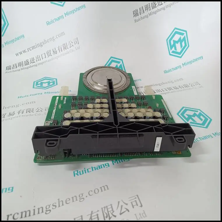
NXPP-06C NXPP06C 应DCS系统适配器主板 ABB
e应使用通用安装支架,以避免与
导电结构。
3.将分接电缆连接至BNC连接器。在启动
系统,应测试所有控制网电缆连接。检查牵引力
应用连接器的强度。
4.定义网络节点地址:
–机架输入/输出-通过转动200前面的两个开关(x10和x1)-
RACN模块至正确位置。范围为02-99的节点地址
应为200个RACN选择。
–200系列I/O-通过单击
200-ACN模块。应选择范围为02-99的节点地址
对于200个ACN。
–CI865-节点地址固定为01。
安装Modbus TCP接口CI867/TP867第2节安装
136 3BSE036351-600 A
安装Modbus TCP接口CI867/TP867
CI867由处理器单元通过CEX总线供电,无需额外电源
需要外部电源。
使用以下步骤安装CI867/TP867:
1.将装置安装到DIN导轨上,请参阅第71页的“将AC 800M装置安装到DinRail上”和中的“安装PM85x/PM86x/TP830处理器装置”
单一配置见第84页。
2.将10/100Mbps以太网双绞线连接到上的CH1连接器
底板。
3.通过将以太网电缆的另一端连接到快速以太网网络
标准以太网组件。
4.将10Mbps以太网双绞线连接到
底板。
5.通过标准将以太网电缆的另一端连接到以太网
以太网组件。
以太网双绞线连接
快速10/100 Mbps以太网双绞线通过RJ45连接器连接
(CH1)位于TP867上。较慢的10 Mbps以太网双绞线通过
位于TP867上的RJ45连接器(CH2)。
有关连接器的说明,请参见第90页的表5。
第2节安装安装IEC 61850接口CI868
3BSE036351-600 A 137
安装IEC 61850接口CI868
CI868由处理器单元通过CEX总线供电,无需额外电源
需要外部电源。
要安装CI868:
1.将装置安装到DIN导轨上,参见第71页的“将AC 800M装置安装到DINRAIL上”。
2.将100Mbps以太网双绞线连接到
底板。
3.通过将以太网电缆的另一端连接到快速以太网网络
标准以太网组件。请参阅PTUST04-3211-交换机管理
适用于IEC 61850,适用于经IEC 61850认证的开关。
安装AF 100接口CI869
CI869单元由处理器单元通过CEX总线供电,无
需要额外的外部电源。
要安装CI869:
1.将CI869装置安装到DIN导轨上。参见将AC 800M装置安装到
DIN导轨,第71页。
2.将AF 100双绞线连接至CI869的4针触点。
如果是冗余介质,将另一个AF 100双绞线连接到另一个
4针触点。
3.将双绞线的另一端连接到AF 100总线。
有关AF 100连接的详细信息,请参阅Advant现场总线100用户手册
(3BSE000506*)。
安装PROFINET IO接口CI871第2节安装
138 3BSE036351-600 A
安装PROFINET I
NXPP-06C NXPP06C 应DCS系统适配器主板 ABB
NXPP-06C NXPP06C 应DCS系统适配器主板 ABB
NXPP-06C NXPP06C 应DCS系统适配器主板 ABB
e universal mounting bracket should be used to avoid galvanic connection to
a conducting structure.
3. Connect the tap drop cable to the BNC connector. Before starting up the
system, all ControlNet cable connections should be tested. Check the pulling
strength of applied connectors.
4. Define the network node address:
– Rack I/O - by turning the two switches (x10 and x1) on front of the 200-
RACN module to the correct position. A node address in the range 02-99
should be selected for the 200-RACNs.
– Series 200 I/O - by clicking the push button switches on the front of the
200-ACN module. A node address in the range 02-99 should be selected
for the 200-ACNs.
– CI865 - The node address is fixed to 01.
Installing the Modbus TCP Interface CI867/TP867 Section 2 Installation
136 3BSE036351-600 A
Installing the Modbus TCP Interface CI867/TP867
The CI867 is powered from the processor unit via the CEX-Bus and no additional
external power source is required.
Use the following procedure to install the CI867/TP867:
1. Mount the unit onto the DIN-rail, see Mounting AC 800M Units onto DINRailon page 71 and Installing the PM85x/PM86x/TP830 Processor Unit in
Single Configurationon page 84.
2. Connect the 10/100Mbps Ethernet twisted pair cable to the CH1 connector on
the baseplate.
3. Connect the other end of the Ethernet cable to a Fast Ethernet network via
standard Ethernet components.
4. Connect the 10Mbps Ethernet twisted pair cable to the CH2 connector on the
baseplate.
5. Connect the other end of the Ethernet cable to a Ethernet network via standard
Ethernet components.
Ethernet Twisted Pair Connection
The Fast 10/100 Mbps Ethernet twisted pair is connected via the RJ45 connector
(CH1) located on TP867. The slower 10 Mbps Ethernet twisted pair is connected via
the RJ45 connector (CH2) located on TP867.
For a description of the connectors see Table 5 on page 90.
Section 2 Installation Installing the IEC 61850 Interface CI868
3BSE036351-600 A 137
Installing the IEC 61850 Interface CI868
The CI868 is powered from the processor unit via the CEX-Bus with no additional
external power source required.
To install CI868:
1. Mount the unit onto the DIN-rail, see Mounting AC 800M Units onto DINRailon page 71.
2. Connect the 100Mbps Ethernet twisted pair cable to the CH1 connector on the
baseplate.
3. Connect the other end of the Ethernet cable to a Fast Ethernet network via
standard Ethernet components. Refer to PTUST04-3211- Switch Management
for IEC 61850 for switches that are certified for IEC 61850.
Installing the AF 100 Interface CI869
The CI869 unit is powered from the processor unit via the CEX-Bus with no
additional external power source required.
To install CI869:
1. Mount the CI869 unit onto the DIN-rail. See Mounting AC 800M Units onto
DIN-Rail on page 71.
2. Connect the AF 100 twisted pair to the 4-pin contact of CI869.
In case of redundant media, connect the other AF 100 twisted pair to the other
4-pin contact.
3. Connect the other end of the twisted pair to the AF 100 bus.
For details on AF 100 connections, refer to the Advant Fieldbus 100 User Manual
(3BSE000506*).
Installing the PROFINET IO Interface CI871 Section 2 Installation
138 3BSE036351-600 A
Installing the PROFINET I
NXPP-06C NXPP06C 应DCS系统适配器主板 ABB