- 热插拔产品特性
- 否是否进口
- 美国产地
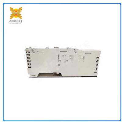
SCHNEIDER 140CRP93100 冗余系统模块
SCHNEIDER 140CRP93100在冗余热备控制系统中,整个PLC控制系统(或系统最重要部分如控制器) 由 2套配置完全相同的PLC主机、电源、冗余处理模块组成。 2个控制器模块使用相同的用户程序并行工作,其中一块是主控制器,另一 块是备用控制器,后者的输出是禁止的。 当主控制器出现故障时,系统立刻投入备用控制器,这一切换过程是由冗余 热备控制处理单元(Redundancy Process Unit,RPU)控制的,I/O系统的切换 也是由RPU实现的。
140CRP93100的几个主要亮点包括单根同轴电缆、300 mA的总线电流和3W的功耗。该模块还获得了ATEXzone 2/22认证,其中包括密集、全面和详细的测试和检查过程。按照这些程序,像这种获得认证的产品也会得到一份报告,概述结果并确认其达到了设定的标准。140CRP93100在模块正面顶部有一个LED功能,位于型号和型号说明的正下方。当模块通过通电诊断时,LED功能将显示绿灯。当模块在RIO网络上通信时,Com Act LED显示绿色。红色故障LED表示无法与一个或多个/O模块通信。对于通道A上的通信错误,错误A LED显示为红色。***,故障BLED显示红色,与错误A—起指示无效的节点地址。
SCHNEIDER 140CRP93100 In a redundant hot standby control system, the entire PLC control system (or the most important part of the system, such as the controller) consists of two sets of PLC hosts with identical configurations, power supplies, and redundant processing modules. Two controller modules work in parallel using the same user program, with one being the main controller and the other being the backup controller, whose output is disabled. When the main controller fails, the system immediately switches to a backup controller. This switching process is controlled by the Redundancy Process Unit (RPU), and the switching of the I/O system is also achieved by the RPU.
The main highlights of 140CRP93100 include a single coaxial cable, a bus current of 300 mA, and a power consumption of 3W. This module has also obtained ATEXzone 2/22 certification, which includes intensive, comprehensive, and detailed testing and inspection processes. According to these procedures, certified products like this will also receive a report outlining the results and confirming that they meet the set standards. 140CRP93100 has an LED function on the top of the front of the module, located directly below the model and model description. When the module undergoes power on diagnosis, the LED function will display a green light. When the module communicates on the RIO network, the Com Act LED displays green. The red fault LED indicates that communication with one or more/O modules is not possible. For communication errors on channel A, the error A LED is displayed in red. Finally, the fault BLED displays in red, along with error A, indicating an invalid node address.
 在线问
在线问
- 热插拔
- 否
- 美国
- 否
- SCHNEIDER
- 140CRP93100
- 220
- 60


