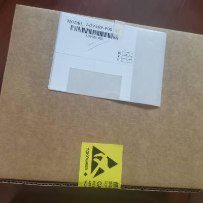
- 标准规格产品特性
- 否是否进口
- 日本产地
A1BR4D-05
n标准规格
关于端子板的安装和环境条件,请参见CENTUM的“安全注意事项”
VP安装指南(TI 33J01J10-01EN),与端子板通用。
型号描述点终端模块
连接
连接
适配器
连接
电缆重量规格
A1BA4D
为模拟
信号
(单和
双冗余
模块)
8分x 1压
夹
AAI135 (* 1)
AAI835 (* 1)
AAP135 (* 1)
ATK4A
0.30公斤
绝缘电阻:
10 MΩ或更高,500v DC
承受电压:
16分x 1500v AC 1分钟(*4)压力
夹
AAI141
AAV141
AAV144
AAB841
AAI841
AAV544
AAI143
AAI543
A1BT4D
为
热电偶
(单和
双冗余
模块)
16分x 1压
夹具AAT145 - (*3) KS1
0.30公斤
绝缘电阻:
200v DC时10 MΩ或更高
承受电压:
200v交流电1分钟(*4)
A1BR4D
为电阻
温度
探测器
(单和
双冗余
模块)
16分x 1压
夹具AAR145 - (*3) AKB335
0.30公斤
绝缘电阻:
200v DC时10 MΩ或更高
承受电压:
200v交流电1分钟(*4)
A1BD5D
(* 6) (* 7)
为数字
信号
(单和
双冗余
模块)
32分x 1压
夹
ADV151
Adv551 atd*** akb331
约。
0.70公斤
绝缘电阻:
10 MΩ或更高,500v DC
承受电压:
2.0 k V AC 1分钟(*5)
ADV161 (* 2)
Adv561 (*2) - (*3) akb337
注意:请务必将连接器帽留在不使用的连接器上,以保护连接器引脚并防止损坏
防止灰尘积聚在上面。
*1:为AAI135/AAI835/AAP135组合;ATK4A;A1BA4D, 2-线发射机2-线输入(发射机
电源类型)或4线制发射器2线制输入(不带发射器电源)可为每个输入选择
通道。
*2: ADV161或ADV561需要A1BD5D两个单位,AKB337两个单位。
*3:电缆可以直接连接到I/O模块,而无需使用适配器。
*4:通道之间
*5:在电源端子和READY端子之间
*6: READY接触等级如下所示。
125v AC及以下,0.3 A及以下
60v DC及以下,1a及以下
*7:外接电源电压如下图所示。
24v dc±10%
逐句对照
支持a1ba4d, a1bd5d, a1br4d
适用的电缆
参考TI“CENTUM VP安装指南”(TI 33J01J10-01EN),并使用合适的电缆
其安装环境。
电缆的额定温度
型号电缆电缆的温度等级
A1BA4D、A1BR4D信号线环境温度≥10℃
A1BD5D
信号电缆
(含READY端子)环境温度≥10℃
输入电源线环境温度≥20℃
推荐电线标称截面积
•压力夹端子
无套筒:0.5至2 mm2 (AWG20至14)
采用压夹端子的电缆终端工艺
•没有袖子
电线标称横截面积(mm2
剥脱长度(mm)
0.5 ~ 2.5 (AWG20 ~ 14
•带袖子
建议使用以下任何一种套筒。
带绝缘盖的套管(DIN 46 228/4)
电缆的名义
横截面
区域
(平方毫米
)
当使用有绝缘套的套筒时,当使用没有绝缘套的套筒时
绝缘罩
剥离长度
(毫米)
套筒尺寸(mm)拆下长度
(毫米)
袖
尺寸(毫米)
总计
长度
接触的部分
长度
总计
长度
0.5 10 14 8 6 6
0.75 10 14 8 6 6
1.0 10 14 8 6 6
1.5 10 14 8 7 7
2.5 10 14 8 7 7
l A1BT4D
适用的电缆
参考TI“CENTUM VP安装指南”(TI 33J01J10-01EN),并使用合适的电缆
其安装环境。
电缆的额定温度
型号电缆电缆的温度等级
A1BT4D信号线环境温度≥10℃
推荐电线标称截面积
•压力夹端子
无套筒:0.5至2 mm2 (AWG20至14)
带套筒:0.5至1.5 mm2 (AWG20至16)
Cable Termination Process when Pressure Clamp Terminals are Used
• Without a Sleeve
Wire nominal cross sectional area (mm2
) Peel-off length (mm)
0.5 to 2 (AWG20 to 14) 11
• With a Sleeve
It is recommended to use any one of the following sleeves.
Sleeve without insulating cover (DIN 46 228/1) Sleeve with insulating cover (DIN 46 228/4)
Cable nominal
cross sectional
area
(mm2
)
When using a sleeve with insulating cover When using a sleeve without
insulating cover
Peel-off length
(mm)
Sleeve dimensions (mm) Peel-off
length
(mm)
Sleeve
dimensions (mm)
Total
length
Contact section
length
Total
length
0.5 12 16 10 10 10
0.75 12 16 10 10 10
1.0 12 16 10 10 10
1.25 to 1.5 12 16 10 10 10
n TERMINAL BLOCK AND CONNECTOR CONNECTION SPECIFICATIONS
Please refer to the specifications shown below to connect signal cables with a proper terminal since some Analog I/O
modules require to select a proper terminal dependent on the devices to be connected.
Models Cable
Connection Pris Input Type
AAI141
AAI143
AAI841
(*1)
INA 2-wire transmitter input + Current input -
— INB 2-wire transmitter input -
(setting pin: 2-wire input)
Current input +
(setting pin: 4-wire input)
AAI135
AAI835
INA 2-wire transmitter input + —
INB 2-wire transmitter input - Current input + —
INC — Current input -
AAR145
(*2)
INA RTD input A POT input, 100 %
INB RTD input B POT input, 0 % —
INC RTD input B POT input, variable
AAP135
INA 2-wire power supply (power) – 3-wire power supply power supply
INB 2-wire power supply (signal) 2-wire (voltage, contact) + 3-wire power supply +
INC — 2-wire (voltage, contact) - 3-wire power supply -
is channel number.
*1: When power of models AAI141, AAI143, AAI841, AAI135 and AAI835 is off or abnormal, current input loop is in the open
state.
Do not use current signals with other receiving devices.When in use, also use an extarnal receiver resistance, in the
voltage mode (Shunt resistant module part no.: A1080RZ 250 ohm).
*2: Wiring resistance for the signal cables of INA and INB must be identical.
 在线问
在线问
- 标准规格
- 否
- 日本
- 否
- YOKOGAWA/横河
- A1BR4D-05
- 数字输入输出模块
- 支持双冗余配置
- 输入通道数32 64
- CE
- 状态输入检测功能
- 1
- H50


