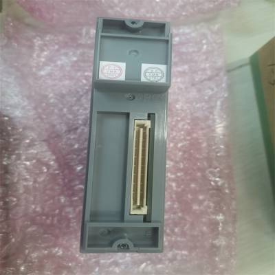
- 标准规格产品特性
- 否是否进口
- 日本产地
AET4D-05
本指南涵盖了可以安装在ESB中的数字I/O模块(FIO)的硬件规范
总线节点单元(ANB10S、ANB10D)、光ESB总线节点单元(ANB11S、ANB11D)和现场控制单元
(afv30s, afv30d, afv40s, afv40d)。
n标准规格
l数字输入模块
数字输入模块接收32路或64路24v DC开/关信号。
ADV151和ADV161支持双冗余配置。
项规范
ADV151-P/ADV151-E (*1
输入通道数32 64
额定输入电压(*2)24v DC(汇/源)24v DC(汇/源)
输入ON电压18 ~ 26.4 V DC 20 ~ 26.4 V DC
输入OFF电压≤5.0 V DC≤5.0 V DC
输入电流(额定输入电压下)4.1 mA±20% /通道2.5 mA±20% /通道
允许输入电压30.0 V DC 30.0 V DC
输入信号与系统之间的耐压:2kv交流,持续1分钟
共路间:500v AC,每16路共路1分钟(*3)
功能
状态输入检测功能
开/关状态
检测功能
开/关状态
按钮输入按钮边缘计数功能按钮边缘计数功能
SOE input捕获SOE数据的功能
输入响应时间小于等于8毫秒(对于状态输入)
最小ON检测时间20ms(按钮输入)
开/关周期25hz(用于按钮输入)
电流消耗500ma (5v DC) 550 mA (5v DC)
重量约0.30 kg
外部连接
压钳端子,
专用电缆(AKB331);
MIL连接器电缆
专用电缆(AKB337);
MIL连接器电缆
*1:不支持在ER总线节点单元中安装ADV151-E。
*2:每16通道共用ADV151和ADV161。所有待连接的电压输入信号(24v DC)必须在
相同的极性。
*3:使用专用电缆的耐压电压为500v AC(输入信号与系统之间)。
MIL连接器电缆的耐压取决于其电缆的电气规格
l Digital Output Modules
The Digital Output Modules output 32-channel or 64-channel transistor contact signals.
The ADV551 and ADV561 can be used in dual redundant configuration.
Item Specifications
Model ADV551 ADV561
Number of output channels 32 64
Rated applied voltage 24 V DC 24 V DC
Load voltage 24 V DC, 50 mA 24 V DC, 100 mA
External power supply voltage
range
20.4 to 26.4 V DC 20.4 to 26.4 V DC
Output ON voltage maximum
value 2 V DC 2 V DC
Leak current maximum value
when output OFF 0.1 mA 0.1 mA
Output format Current sink Current sink
Maximum load current (*1) 100 mA/channel, 26.4 V 100 mA/channel, 26.4 V
Withstanding voltage Between output signal and system: 2 kV AC, For 1 minute Between commons: 500 V AC, For 1
minute, common minus (–) side every 16-channel (*2)
Functions
Status output ON/OFF status output function ON/OFF status output function
Pulse width output One-shot pulse width output function One-shot pulse width output function
Time-proportioning output Time-proportioning ON/OFF Time-proportioning ON/OFF
Output response time 3 ms or less (for status output)
10 ms or less (for mixed status and pulse outputs)
Pulse width 8 ms to 7200 s
Pulse width resolution 8 ms, but ON/OFF delay of maximum 1 ms is added
Maximum current
consumption
700 mA (5 V DC)
60 mA (external power supply)
700 mA (5 V DC)
120 mA (external power supply)
Weight Approx. 0.20 kg Approx. 0.30 kg
External connection Pressure clamp terminal,
Dedicated cable (AKB331), MIL connector cable Dedicated cable (AKB337), MIL connector cable
*1: Connect a spark killer diode when driving DC relay.
*2: The withstanding voltage for using a dedicated cable is 500 V AC (between output signal and system).
The withstanding voltage for using MIL connector cable depends on the electrical specifications of its cable.
l Digital I/O Modules (CENTUM-ST Compatible)
The Digital I/O Modules (CENTUM-ST Compatible) receive contact or voltage status signals from the field, and/or
output status signals to the field via transistor contacts.
Item Specifications
Model ADV859 ADV159 ADV559
Number of I/O channels 16-channel input,
16-channel output 32-channel input 32-channel output
Signal ***lation ***lated channels ***lated channels ***lated channels
Input signal
Contact input: OFF signal 100 kΩ or more
ON signal 200 Ω or less
Minimum current value when contact is shortcircuited: 1.25 mA
Voltage input: OFF signal 4.5 to 25 V DC
ON signal ±1 V DC, 200 Ω or less
—
Input contact rating 5 V DC, 20 mA or more —
Pushbutton input function Not supported Supported —
Input response time 8 ms (for status input) 8 ms (for status input) —
Minimum ON detection time — 20 ms (for pushbutton input) —
Maximum ON/OFF cycle — 25 Hz (for pushbutton input) —
Output signal Transistor contact — Transistor contact
Output contact rating Inductive load, resistive load:
30 V DC, 100 mA (*1) — Inductive load, resistive load:
30 V DC, 100 mA (*1)
Output response time 16 ms or less — 16 ms or less
Pulse width 8 ms to 7200 s — 8 ms to 7200 s
Pulse width resolution 8 ms, add max. 1ms for ON/OFF
delay time — 8 ms, add max. 1ms for ON/OFF
delay time
Maximum current
consumption 450 mA (5 V DC) 330 mA (5 V DC) 570 mA (5 V DC)
Weight Approx. 0.30 kg Approx. 0.40 kg Approx. 0.30 kg
External connection Dedicated cable (KS2) Dedicated cable (KS2) Dedicated cable (KS2)
Compatible card ST2 compatible ST3 compatible ST4 compatible
*1: Connect a spark killer diode when driving DC relay.
Item Specifications
Model ADV869 ADV169 ADV569
Number of I/O channels 32-channel input,
32-channel output 64-channel input 64-channel output
Signal ***lation Common every 16-channel Common every 16-channel Common every 16-channel
Input signal
Contact input: OFF signal 100 kΩ or more
ON signal 200 Ω or less
Minimum current value when contact is shortcircuited: 1.25 mA
Voltage input: OFF signal 4.5 to 25 V DC
ON signal ±1 V DC, 200 Ω or less
—
Input contact rating 5 V DC, 20 mA or more —
Pushbutton input function Not supported Not supported —
Input response time 8 ms (for status input) 8 ms (for status input) —
Output signal Transistor contact — Transistor contact
Output contact rating Inductive load, resistive load:
30 V DC, 100 mA (*1) — Inductive load, resistive load:
30 V DC, 100 mA (*1)
Output response time 16 ms or less — 16 ms or less
Pulse width 8 ms to 7200 s — 8 ms to 7200 s
Pulse width resolution 8 ms, add max. 1 ms for ON/
OFF delay time — 8 ms, add max. 1 ms for ON/
OFF delay time
Maximum current
consumption 800 mA (5 V DC) 800 mA (5 V DC) 800 mA (5 V DC)
Weight Approx. 0.30 kg Approx. 0.30 kg Approx. 0.30 kg
External connection Dedicated cable (KS9) Dedicated cable (KS9) Dedicated cable (KS9)
Compatible card ST5 compatible ST6 compatible ST7 compatible
 在线问
在线问
- 标准规格
- 否
- 日本
- 否
- YOKOGAWA/横河
- AET4D-05
- 型数字输入模块
- 具有脉宽输出功能
- 时间比例输出功能
- CE
- 具有防爆功能
- 1
- H50


