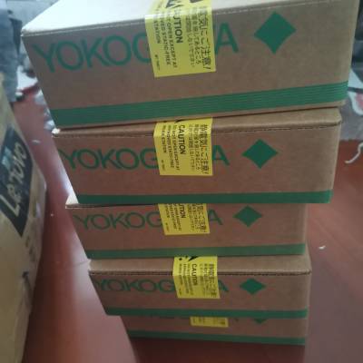
- 标准规格产品特性
- 否是否进口
- 日本产地
AAI835-S50
脉冲输入模块(隔离通道)
该模块接收触点开/关、电压脉冲和电流脉冲信号。它被隔离在田野和
该系统还可在各通道之间配置,并可采用双冗余配置。
项目规范
模型AAP135
输入通道数8,隔离通道
输入信号(*3)
2线式:触点开/关,电压脉冲,电流脉冲
(可提供发射机电源)
3线式:电源式电压脉冲
输入频率0 ~ 10khz (*4)
输入与系统之间:500v AC,持续1分钟
通道间:500v AC,持续1分钟(*1)
最小输入脉冲宽度40µs
输入信号电平
接点输入
继电器触点和晶体管触点的开/关电平
开盘价:100 kΩ或以上,收盘价:200 Ω或以下
触点容量
供电12v DC时:15v DC 15ma或更高
供电24v DC时:30v DC 30ma或更高
电压/电流脉冲输入(电流输入转换为电压)
VH(高电平):3 ~ 24v DC
VL(低电平):-1 ~ 8v DC
VH-VL(摆幅值):3v或更高
信号源电阻:1 kΩ以下
分流电阻可从无/200/500/1000 Ω中选择。
(断电时开启,双冗余配置备用侧开启)
上拉电阻68 kΩ (12v DC或24v DC)
可设置消除抖振的滤波器。(* 2)
数据更新周期为2ms
发射机电源可选择24v DC/ 12v DC。
限幅值12v DC±10%:40ma, 24v DC±10%:30ma
电流消耗300ma (5v DC), 400ma (24v DC)
重量0.3 kg
外部连接压力夹端子,KS电缆,MIL连接器电缆
*1:使用ML连接器电缆时,耐压取决于电缆的电气规格。
*2:当脉冲输入信号为干接点(如机械继电器)高达10hz时,可以消除抖振。
*3:与现场设备的连接方式因输入信号而异。参考安装指南(TI 33K01J10-50E)
细节。
*4: B、C端子之间输入频率为0 ~ 800hz,接收无电压接触信号。
兼容PM1脉冲输入模块
该模块通过接收来自脉冲序列输入信号调理卡的16通道脉冲序列信号来计数脉冲。
项目规范
模型AAP149
输入通道数16,非隔离
输入信号晶体管触点(开路集电极)
输入频率0 ~ 6khz
耐电压
脉冲检测边缘后缘
数据更新周期为2ms
电流消耗400ma (5v DC)
重量0.3 kg
外部连接专用线缆(KS2)
逐句对照
脉冲输入模块/模拟输出模块兼容PAC
该模块接收8通道脉冲序列信号,输出4 ~ 20mA信号。它可以用于双冗余
配置。
项目规范
模型AAP849
I/O通道数8通道输入/8通道输出,非隔离
I/O信号输入:晶体管触点(开路集电极)输出:4至20 mA
输入频率0 ~ 12khz
脉冲检测边缘后缘-
允许负载电阻- 0至750 Ω
电路开路检测-小于0.65 mA
精度-±48µA
数据更新周期为1ms ~ 10ms
输出阶跃响应时间- 40毫秒
温度漂移-±16µA/10°C
电流消耗310ma (5v DC), 250ma (24v DC) -
重量0.3 kg
外部连接专用电缆(KS1)
操作环境
硬件需求
模拟I/O模块在以下FCS上运行。
afv30, afv30d, afv40, afv40d, afv10, afv10d,
afs30, afs30d, afs40, afs40d,
afg30, afg30d, afg40, afg40d,
Afg81s, afg81d, afg82s, afg82d, afg83s, afg83d, afg84s, afg84d,
AFF50S和AFF50D
软件需求
模拟I/O模块运行在以下FCS的控制功能上。
LFS1700现场控制站控制功能(适用于AFV30/AFV40、Vnet/IP和FIO):
对于AFV30/ AFV40
LFS1500现场控制站控制功能(适用于AFV10,Vnet/IP和FIO):适用于AFV10
LFS1300用于标准现场控制站的控制功能(用于V网和FIO):用于AFS30/AFS40
LFS1330增强型现场控制站控制功能(适用于V网和FIO):
用于AFG30/AFG40/AFG8
LFS1350紧凑型现场控制站控制功能(用于V网和FIO):用于AFF50
工程要求
适用于LHS5100/LHMS5100标准构建器功能。
ANALOG I/O MODULE (WITH HART COMMUNICATION)
The analog I/O module (with HART communication function) connected to a transmitter or a valve positioner receives
HART variable (*1) in addition to exchange analog input/output data by 4 – 20 mA signal with field control stations
(FCS). There are 8 types of analog I/O modules (with HART communication function).
*1: HART variable can be read by HART Command #3.
There are 8 types of analog I/O modules (with HART communication function).
Model Model Name Function
AAI141-H Analog Input Module (Current Input) 16-channel, 4 to 20 mA, non-***lated
AAB141-H Analog Input Module (Voltage/current Input) 16-channel, 1 to 5 V/4 to 20 mA, non-***lated
AAI841-H Analog I/O Module (Current I/O) 8-channel input/8-channel output, 4 to 20 mA, non-***lated
AAB842-H Analog I/O Module
(Voltage/current Input, Current Output)
8-channel input/8-channel output, 1 to 5 V/4 to 20 mA input,
4 to 20 mA output, non-***lated
AAI135-H Analog Input Module (Current Input) 8-channel, 4 to 20 mA, ***lated channels
AAI835-H Analog I/O Module (Current I/O) 4-channel input/4-channel output, 4 to 20 mA, ***lated channels
AAI143-H Analog Input Module (Current Input) 16-channel, 4 to 20 mA, ***lated
AAI543-H Analog Output Module (Current Output) 16-channel, 4 to 20 mA, ***lated
Communication with HART Devices
The analog I/O modules (with HART communication function) communicate with field devices and store analog data
and HART variables in the Input/Output image area in the communication module. An FCS refers to and sets the
Input/Output image by accessing the analog I/O modules (with HART communication function). The FCS utilizes the
field device data via I/O terminals of the function block in the same way as other analog/digital I/O signals
 在线问
在线问
- 标准规格
- 否
- 日本
- 否
- YOKOGAWA/横河
- AAI835-S50
- 电流/电压输入模块(非隔离)
- 允许共模电压
- 输入通道数16,非隔离16,非隔离
- CE
- 精度±16µA±4mv
- 1
- S00


