产品介绍Product introduction

产品信息产品类别:模块卡件
品牌:DCS、PLC
电话:15270269218
联系人:叶经理
质保期:1年
加工定制:不可定制
产地/厂家:美国
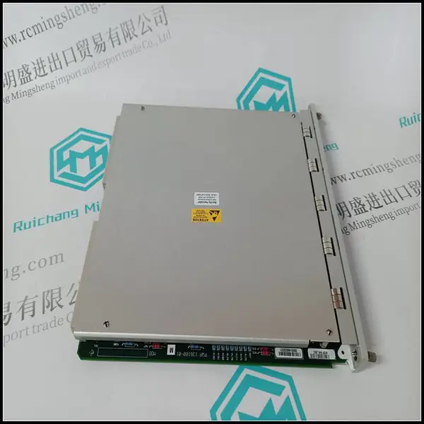
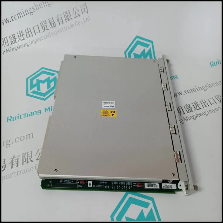
产品实拍图Product picture
调谐。您也可以放弃自动调谐。在这里
时间,请输入电机铭牌上的值
正确(FH.00~FH.02)。
如果无法应用自动调谐,并且正确的电机
参数可用,用户应输入值
在电机铭牌上正确显示(FH.00~FH.02),以及
然后输入计算值(FH.03~FH.07)。一定要
正确设置参数。
如果自动调谐不成功,驱动器将报警并
显示故障代码E024。
FH。10电机的稳定
因素
范围:0~255【相关
在驱动器型号上。]
FH。10用于抑制由
驱动器和电机。如果驱动器的输出电流发生变化
通常在恒定负载下,您可以减少
通过调整参数进行振荡。
对于55kW或以下的驱动,FH。10被设置为10,并且
“20”用于55kW或以上的驱动。
FH.11~FH。21保留
保留
5.14保护功能(FL组)
FL.00电机过载
保护模式选择范围:0.1.2【1】
0:禁用
过载保护被禁用。小心使用
此功能是因为驱动器不会保护电机
发生过载时;
第5章参数介绍79
EV2000系列通用变速驱动用户手册
1: 共模(带低速补偿)
因为普通电机的冷却效果恶化
低速(低于30Hz)时,电机过热
应降低保护阈值,这称为
低速补偿。
2: 变频电机(无低速
补偿)
变频电机的冷却效果不是
受电机速度的影响,所以速度较低
不需要补偿。
FL.01电机过载
保护系数
范围:20.0~110.0%
【100.0%】
为了对不同的应用***过载保护
电机种类,驱动的输出电流
应如图5-71所示进行调整。
电机过载
防护的
系数
80% ***
1分钟
时间
160%至200%电流
图5-71电机过载保护系数
使用以下系数计算系数:
电机过载
保护系数
电机额定电流
逆变器的额定输出电流
= ×***
通常,负载电流是电机的额定电流
现在的
注:
如果电机的额定电流与驱动器的额定电流不匹配,
电机的过载保护可通过设置实现
FL.00~FL.01。
FL.02保护
失速范围过电压:0.1【1】
FL.03过电压点
货摊
范围:120~150%
【140.0%】
0:禁用
1: 启用
减速期间,电机的减速率可能为
低于驱动器的输出频率,因为
负载惯性。此时,电机将提供能量
返回驱动器,导致
驱动器的直流总线。如果不采取措施,驱动器将跳闸
由于过电压。
在减速过程中,驱动器检测到总线
电压,并将其与过电压点进行比较
FL.03定义的失速。如果总线电压超过
失速过电压点,驱动器将停止降低其
输出频率。当总线电压变低时
然后,减速继续,如中所示
图5-72。
过电压
指向
货摊
输出
频率。
时间
时间
图5-72失速时的过电压
注:
当驱动器处于以下位置时,驱动器将报警并显示E015:
失速时的过电压状态超过1分钟。
如果失速点设置得太低,您可以延长Acc和
12月是适当的时间。
FL.04过载检测范围:000~111【000】
FL.05过载预报警
检测阈值
范围:20~150%
【130.0%】
FL.06过载检测时间范围:0.0~60.0s【5.0s】
EV2000具有驱动和电机过载保护。
驱动器过载保护见表2-1,FL.00
FL.01用于电机过载保护。FL.04~FL.06
可在过载前监测过载情况
保护发生了。
A、B、C、D
过载报警检测
0:始终检测
1: 恒速状态下的检测
过载保护
0:无报警,继续运行
1: 报警和停止操作
过载检测阈值
电机额定电流的0%
1: 驱动器额定电流的***比
保留
图5-73 FL.0的设置
to-tuning. You can also give up the auto-tuning. At this
time, please input the values on the motor’s nameplate
correctly (FH.00~FH.02).
If the auto-tuning cannot be applied and the correct motor’s
parameters are available, the user should input the values
on the motor’s nameplate correctly (FH.00~FH.02), and
then input the calculated values (FH.03~FH.07). Be sure to
set the parameters correctly.
If auto-tuning is not successful, the drive will alarm and
display fault code E024.
FH.10 Motor’s stabilization
factor
Range:0~255【dependent
on drive’s model】
FH.10 is used to suppress the oscillation caused by the
drive and the motor. If the drive’s output current changes
frequently at constant load, you can reduce the
oscillation by adjusting the parameter.
For the drive of 55kW or below, FH.10 is set at 10, and
“20” for the drive of 55kW or above.
FH.11~FH.21 Reserved
Reserved
5.14 Protective Function (Group FL)
FL.00 Motor overload
protection mode selection Range:0. 1. 2【1】
0: Disabled
The overload protection is disabled. Be careful to use
this function because the drive will not protect the motor
when overload occurs;
Chapter 5 Parameter Introductions 79
EV2000 Series Universal Variable Speed Drive User Manual
1:Common mode (with low speed compensation)
Since the cooling effects of common motor deteriorates
at low speed (below 30Hz), the motor’s overheat
protecting threshold should be lowered, which is called
low speed compensation.
2: Variable frequency motor (without low speed
compensation)
The cooling effects of variable frequency motor is not
affected by the motor’s speed, so low speed
compensation is not necessary.
FL.01 Motor’s overload
protection coefficient
Range:20.0~110.0%
【100.0%】
In order to apply effective overload protection to different
kinds of motors, the Max output current of the drive
should be adjusted as shown in Fig. 5-71.
Motor overload
protective
coefficient
80% ***
1min
Time
160% 200% Current
Fig. 5-71 Motor’s overload protection coefficient
Use the following coefficient to calculate the coefficient:
Motor overload
protection coefficient
motor rated current
inverter's rated output current
= ×***
Generally, the Max load current is the motor’s rated
current.
Note:
If the motor’s rated current does not match that of the drive,
motor’s overload protection can be realized by setting
FL.00~FL.01.
FL.02 Protection of
Over-voltage at stall Range:0. 1【1】
FL.03 Over-voltage point at
stall
Range:120~150%
【140.0%】
0: Disabled
1: Enabled
During deceleration, the motor’s decelerate rate may be
lower than that of drive’s output frequency due to the
load inertia. At this time, the motor will feed the energy
back to the drive, resulting in the voltage rise on the
drive's DC bus. If no measures taken, the drive will trip
due to over voltage.
During the deceleration, the drive detects the bus
voltage and compares it with the over voltage point at
stall defined by FL.03. If the bus voltage exceeds the
stall overvoltage point, the drive will stop reducing its
output frequency. When the bus voltage become lower
than the point, the deceleration continues, as shown in
Fig. 5-72.
Overvolt
point at
stall
Output
freq.
Time
Time
Fig. 5-72 Over-voltage at stall
Note:
The drive will alarm and display E015 when it is in the
status of over-voltage at stall for more than 1 minute.
If the stall point is set too low, you can prolong the Acc and
Dec time properly.
FL.04 Overload detection Range:000~111【000】
FL.05 Overload pre-alarm
detection threshold
Range:20~150%
【130.0%】
FL.06 Overload detection time Range:0.0~60.0s【5.0s】
EV2000 has protection over drive and motor overload.
See Table 2-1 for drive overload protection, and FL.00
and FL.01 for motor overload protection. FL.04~FL.06
can monitor the overload condition before overload
protection happens.
A B C D
Overload alarm detection
0: Detect all the time
1: Detect in constant speed status
Overload protection
0: No alarm and continue operation
1: Alarm and stop operation
Overload detection threshold
0: % of motor's rated current
1: % of drive's rated current
Reserved
Fig. 5-73 Settings of FL.0