产品介绍Product introduction

产品信息产品类别:模块卡件
品牌:DCS、PLC
电话:15270269218
联系人:叶经理
质保期:1年
加工定制:不可定制
产地/厂家:美国
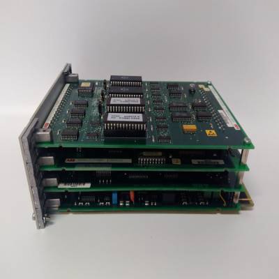
产品实拍图Product picture
安装TRIO现场总线接口CI862
CI862由处理器单元通过CEX总线供电,无需
额外的外部电源。CI862不为现场设备供电。
使用以下步骤安装CI862:
1.将装置安装到DIN导轨上。
2.将现场总线电缆连接到LAN连接器(最右边的连接器)。看见
CI862 TRIO现场总线安装手册指南、电缆类型和
长
手持式显示器(如果使用)连接到HHM连接器。
装置至底板Alpha代码锁
由于以下原因,CI862装置和底板的锁定装置已拆除:
将电子设备放置在装置内。电子设备将不允许CI862
装置应安装在任何带有锁定装置的底板中。然而,其他单位
可插入CI862基板。
总线终端
适当的端接电阻器必须连接到起点和终点
公共汽车的。表142列出了每种类型电缆的特性阻抗。
如果CI862位于总线的两端,则特性电阻由开关设置
在现场总线接口模块上,表17。如果一个TRIO模块在开始
或总线的末端,总线可通过电阻器或终端进行端接
电阻插头,6202FP00150用于150W或6202FP00075用于75W。BSM短截线
不应终止。
CI862基板没有锁定装置。仅将CI862单元插入其中
底板。插入其他装置类型可能会损坏设备。
表17.CI862的现场总线终端开关设置
拨码开关(1)设置
1.75欧姆
2 110欧姆(2)
第2节总线终端的安装
3BSE036351-510 A 125
如图78所示,当出现以下情况时,拨码开关位于外壳底部
从前面看。开关1朝向壳体顶部。
3150欧姆
4.未使用
(1) dip开关必须闭合以进行终端连接。这个
默认为打开(无内部终止)。
(2) 110欧姆选项可用于使用
阻抗范围为100至120欧姆。
表17.CI862的现场总线终端开关设置(续)
拨码开关(1)设置
安装Satt I/O单元和CI865模块第2节安装
126 3BSE036351-510 A
安装Satt I/O单元和CI865模块
CI865由处理器单元通过CEX总线供电,无需
额外的外部电源。CI865不为现场设备供电。
使用以下步骤将ControlNet连接到的BNC连接器
I/O系统和CI865模块。有关更多信息,请参阅的Satt I/O接口
AC 800M(3BSE042821*)。
BNC连接器位于:
•机架I/O-位于200-RACN模块后部。
•200系列I/O-位于200-ACN模块的前部。
•CI865-位于CI865模块的前部。
1.在距控制网一米的范围内为抽头选择合适的位置
BNC连接器。选择抽头位置时,请记住
分接电缆和中继电缆。它们不应靠近高压布线
电缆。避免过度弯曲主干电缆。
2.分接头可以多种方式安装,例如使用DIN导轨或
拧入合适的结构中。即使抽头未安装在DIN导轨上,
应使用通用安装支架,以避免与
导电结构。
3.将分接电缆连接到BNC连接器。在启动之前
系统,应测试所有ControlNet电缆连接。检查拉力
应用连接器的强度。
4.定义网络节点地址:
–机架I/O-通过转动200前面的两个开关(x10和x1)-
RACN模块至正确位置。范围为02-99的节点地址
应为200个RACN选择。
–200系列I/O-通过单击前部的按钮开关
200-ACN模块。应选择范围为02-99的节点地址
对于200个ACN。
–CI865-节点地址固定为01。
第2节安装:安装Modb
Installing the TRIO Fieldbus Interface CI862
The CI862 is powered from the processor unit via the CEX-Bus and requires no
additional external power source. No field device is powered from the CI862.
Use the following procedure to install the CI862:
1. Mount the unit onto the DIN-rail.
2. Connect the field bus cable to the LAN connector (right most connector). See
the CI862 Installation book for TRIO field bus guidelines, cable types and
length.
The Hand-Held Monitor, if used, is connected to the HHM connector.
Unit to Baseplate Alpha Code Lock
The CI862 unit and baseplate have the locking device removed because of the
placement of the electronics inside the unit. The electronics will not allow the CI862
unit to be installed in any baseplate with a locking device. However, other units
could be inserted into the CI862 baseplate.
Bus Termination
The appropriate terminating resistor must be attached to both the beginning and end
of the bus. The characteristic impedance for each type of cable is listed in Table 142.
If the CI862 is at either end of the bus, the characteristic resistance is set by a switch
on the Field Bus Interface Module, Table 17. If a TRIO module is at the beginning
or end of the bus, the bus can be terminated with a resistor or a terminating
resistance plug, 6202FP00150 for 150 W or 6202FP00075 for 75 W. BSM stubs
should not be terminated.
The CI862 baseplate has no locking device. Insert only the CI862 unit into this
baseplate. Insertion of other unit types may cause damage to the equipment.
Table 17. Field Bus Termination Switch Settings of the CI862
Dip Switch(1) Setting
1 75 ohms
2 110 ohms(2)
Section 2 Installation Bus Termination
3BSE036351-510 A 125
As shown in Figure 78, the dip switch is located on the bottom of the housing when
looking from the front. Switch 1 is towards the top of the housing.
3 150 ohms
4 Not Used
(1) The dip switch must be closed to make the termination connection. The
default is open, (no internal termination).
(2) The 110 ohm option may be used to terminate cables with an
impedance in the range of 100 to 120 ohms.
Table 17. Field Bus Termination Switch Settings of the CI862 (Continued)
Dip Switch(1) Setting
Installing the Satt I/O Units and CI865 Module Section 2 Installation
126 3BSE036351-510 A
Installing the Satt I/O Units and CI865 Module
The CI865 is powered from the processor unit via the CEX-Bus and requires no
additional external power source. No field device is powered from the CI865.
Use the following procedure to connect the ControlNet to the BNC connector of the
I/O systems and the CI865 module. For more information see Satt I/O Interface for
AC 800M (3BSE042821*).
The BNC connector is located:
• Rack I/O - at the rear of the 200-RACN module.
• Series 200 I/O - at the front of the 200-ACN module.
• CI865 - at the front of the CI865 module.
1. Select a suitable location for the tap within one meter from the ControlNet
BNC connector. When selecting the tap location, keep in mind the routing of
the drop and trunk cables. They should not be routed close to high-voltage
cables. Avoid bending the trunk cable too much.
2. The tap can be mounted in various ways, for example using a DIN rail or
screwed into a suitable structure. Even if the tap is not mounted on a DIN rail,
the universal mounting bracket should be used to avoid galvanic connection to
a conducting structure.
3. Connect the tap drop cable to the BNC connector. Before starting up the
system, all ControlNet cable connections should be tested. Check the pulling
strength of applied connectors.
4. Define the network node address:
– Rack I/O - by turning the two switches (x10 and x1) on front of the 200-
RACN module to the correct position. A node address in the range 02-99
should be selected for the 200-RACNs.
– Series 200 I/O - by clicking the push button switches on the front of the
200-ACN module. A node address in the range 02-99 should be selected
for the 200-ACNs.
– CI865 - The node address is fixed to 01.
Section 2 Installation Installing the Modb
 DSQC345E工控继电模块PLC库存
¥6973.00
 DSQC346工控继电模块PLC库存
¥6973.00
 DSQC346B工控继电模块PLC库存
¥6973.00
 DSQC346C工控继电模块PLC库存
¥6973.00
 DSQC346E工控继电模块PLC库存
¥6973.00
 DSQC346G工控继电模块PLC库存
¥6973.00


