- 是加工定制
- 爱莎品牌
- 否是否跨境货源
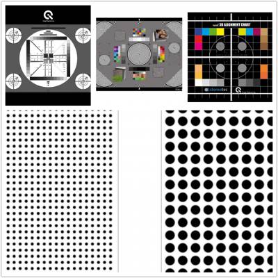
测试卡展示
测试卡说明
测试图被设计用于确定FM亮度边带到下变频的色度频带中的串扰程度,其被解调为不需要的颜色信号(所谓的“交叉颜色”)。
测量电路布置如图1所示。
The test chart is designed for determining the degree of crosstalk of FM-luminance sidebands into the down-converted chrominance band, being demodulated as unwanted color signals (the socalled “cross- color”).
The circuit arrangement for measurement shall be as shown in figure 1.
Conditions of shooting
The subject illumination of a reflective test chart shall be 2000 lx +/- 5%
The luminance of a transparent test chart, at peak white, shall be 636cd/ m2 +/- 5% (= 2000lx)
The non-uniformity of the subject illumination shall be less than 5%
The correlated color temperature of the light source shall be set manually or automatically to 3200K +/- 100K
The test chat shall be shot by the camera so that the frame limited by the arrows exactly coincides with the edges of the picture displayed on the video monitor in underscan mode
The focus control shall be in auto or manual mode and shall be at the best focus
Gain control shall be set to “0 dB” gain
Optical filter shall be set to “open position”
For the measurement of the camera performance the reference luminance level on the camera output is assumed to be 700mV peak-to-peak for PAL and SECAM systems and 714mV peak-to-peak for NTSC system (from the blanking level to the peak white).
The measurement shall be made on the vectorscope screen in measuring the following parameters.
The amplitude of the red vector shall be measured and taken as Vref
The greater amplitude of the color beats signal VLC appearing around the cross point of the vectorscope axes
The amplitude VLC of the color beat signal shall be related to the amplitude Vref of the red vector in order to obtain the degree of luminanced crosstalk as LC
LC (dB) = 20lg (VLC / Vref)

Note: Some transients may be visible on the vectorscope screen due to the luminance components. They should be omitted in this measurement.
 在线问
在线问
- 是
- 爱莎
- 否


