产品介绍Product introduction

产品信息产品类别:模块卡件
品牌:DCS、PLC
电话:15270269218
联系人:叶经理
质保期:1年
加工定制:不可定制
产地/厂家:美国
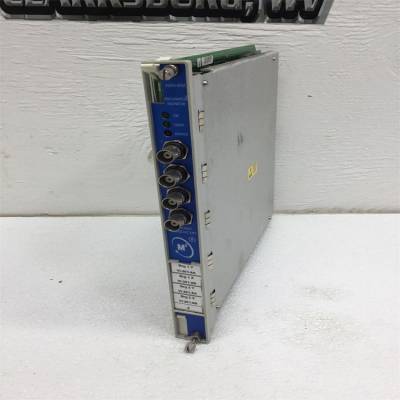
产品实拍图Product picture
错误的参数设置可能导致过热或
电机过流保护。
2.关于fz的定义,请参见F0.21。
3.当驱动器驱动同步电机时,扭矩提升
建议使用函数,V/F曲线应:
可根据电机参数进行调整。
F0.10 Acc时间1范围:0.1~3600s(分钟)【6.0s/20.0s】
F0.11十二月时间1范围:0.1~3600s(分钟)【6.0s/20.0s】
第5章参数介绍45
EV2000系列通用变速驱动用户手册
输出
频率
t1
f值
T2
时间
图5-4 Acc/Dec时间定义
Acc时间是电机加速所需的时间
从0Hz到频率(如F0.04所述),
参见图5-4中的t1。
Dec时间是电机减速所需的时间
从频率(F0.05)到0Hz,参见图中的t2。
5-4.
EV2000系列驱动器定义了4种Acc/Dec
时间此处仅定义了Acc/Dec时间1,以及Acc/Dec
时间2~4将在F3.17~F3.22中定义,请参考
第5.4节。
注:
1.Acc/Dec时间1~4的单位(秒/分钟)取决于
设置为F9.09,默认单位为秒。
2.对于30kW或以上的驱动,出厂设置为
Acc/Dec时间为20.0s。
F0.12上限
频率
范围:频率下限
~输出频率【50.00Hz】
F0.13的下限
频率
范围:0~频率上限
【0.00Hz】
F0.12和F0.13定义了
频率,如图5-2所示,分别为fH和
佛罗里达州。
笔记:
实际输出频率可能超过±2.5Hz in
总线电压控制过程。
F0.14 V/F曲线设置范围:0~3【0】
F0.15 V/F频率值F3范围:F0.17~F0.06
【0.00Hz】
F0.16 V/F电压值V3范围:F0.18~100.0%
【0.0%】
F0.17 V/F频率值F2范围:F0.19~F0.15
【0.00Hz】
F0.18 V/F电压值V2范围:F0.20~F0.16
【0.0%】
F0.19 V/F频率值F1范围:0~F0.17
【0.00Hz】
F0.20 V/F电压值V1范围:0~F0.18【0.0%】
这组参数定义了V/F设置模式
以满足不同的要求
荷载。3条预设曲线和一条自定义曲线可以
根据F0.14的设置进行选择。
如果将F0.14设置为1,则选择2阶曲线,如图所示
在图5-5中为曲线1;
如果F0.14设置为2,则选择1.7阶曲线,如下所示
如图5-5中的曲线2所示;
如果F0.14设置为3,则选择1.2阶曲线,如
如图5-5中的曲线3所示;
上述曲线适用于可变扭矩
风机和泵等负载。您可以选择曲线
根据实际负荷,以达到
节能效果。
0
1.
输出电压(V)
输出频率(Hz)
3 2
f
:输出电压(F0.07)
:基本工作频率(F0.06)
0
Vmax
Vmax
f和b
b
图5-5扭矩减小曲线
如果F0.14设置为0,则可以通过以下方式定义V/F曲线:
F0.15~F0.20,如图5-6所示。V/F曲线可以
通过连接(V1、F1)、(V2、F2)的3个点来定义
以及(V3、F3)以适应特殊负载特性。
出厂设置的默认V/F曲线为直线,如图所示
在图5-5中为曲线0。
电压(%)
Fb频率Hz
***
V1
V2
F1和F2
V3
F3
V1~V3:1~3段电压
F1~F3:1~3段频率
Fb:F0.06的基本工作频率
图5-6 b定义的V/F曲线
Wrong parameter setting can cause overheat or
over-current protection of the motor.
2. Refer to F0.21 for definition of fz.
3. When the drive drives a synchronous motor,torque boost
function is recommended to be used and V/F curve should
be adjusted according to the motor parameters.
F0.10 Acc time 1 Range:0.1~3600s(min)【6.0s/20.0s】
F0.11 Dec time 1 Range:0.1~3600s(min)【6.0s/20.0s】
Chapter 5 Parameter Introductions 45
EV2000 Series Universal Variable Speed Drive User Manual
Output
frequency
t 1
f max
t 2
Time
Fig. 5-4 Acc/Dec time definition
Acc time is the time taken for the motor to accelerate
from 0Hz to the maximum frequency (as set in F0.04),
see t1 in Fig. 5-4.
Dec time is the time taken for the motor to decelerate
from maximum frequency (F0.05) to 0Hz, see t2 in Fig.
5-4.
EV2000 series drive has defined 4 kinds of Acc/Dec
time. Here only Acc/Dec time 1 is defined, and Acc/Dec
time 2~4 will be defined in F3.17~F3.22, please refer to
section 5.4.
Note:
1. Unit(second/minute) of Acc/Dec time 1~4 is dependent
on the setting of F9.09, and the default unit is second.
2. For the drive of 30kW or above, the factory setting of
Acc/Dec time is 20.0s.
F0.12 upper limit of
frequency
Range: Lower limit of frequency
~Max output frequency【50.00Hz】
F0.13 lower limit of
frequency
Range:0~upper limit of frequency
【0.00Hz】
F0.12 and F0.13 define the upper and lower limit of
frequencies respectively, as shown in Fig. 5-2 as fH and
fL.
Notes:
Actual output frequency is possible to exceed ±2.5Hz in
the bus-voltage control process.
F0.14 V/F curve setting Range: 0~3【0】
F0.15 V/F frequency value F3 Range: F0.17~F0.06
【0.00Hz】
F0.16 V/F voltage value V3 Range: F0.18~100.0%
【0.0%】
F0.17 V/F frequency value F2 Range: F0.19~F0.15
【0.00Hz】
F0.18 V/F voltage value V2 Range: F0.20~F0.16
【0.0%】
F0.19 V/F frequency value F1 Range: 0~F0.17
【0.00Hz】
F0.20 V/F voltage value V1 Range:0~F0.18【0.0%】
This group of parameters define the V/F setting modes
of EV2000 so as to satisfy the requirements of different
loads. 3 preset curves and one user-defined curve can
be selected according to the setting of F0.14.
If F0.14 is set to 1, a 2-order curve is selected, as shown
in Fig. 5-5 as curve 1;
If F0.14 is set to 2, a 1.7-order curve is selected, as
shown in Fig. 5-5 as curve 2;
If F0.14 is set to 3, a 1.2-order curve is selected, as
shown in Fig. 5-5 as curve 3;
The above curves are suitable for the variable-torque
loads such as fan & pumps. You can select the curves
according to the actual load so as to achieve best
energy-saving effects.
0
1
Output voltage (V)
Output frequency (Hz)
3 2
f
: Max output voltage(F0.07)
: Basic operating frequency(F0.06)
0
Vmax
Vmax
f b
b
Fig. 5-5 Torque-reducing curve
If F0.14 is set to 0, you can define V/F curve via
F0.15~F0.20, as shown in Fig. 5-6. The V/F curve can
be defined by connecting 3 points of (V1,F1), (V2,F2)
and (V3, F3), to adapt to special load characteristics.
Default V/F curve set by factory is a direct line as show
in Fig. 5-5 as curve 0.
Voltage (%)
Fb Freq Hz
***
V1
V2
F1 F2
V3
F3
V1~V3: Voltage of sections 1~3
F1~F3: Freq of sections 1~3
Fb: Basic operating freq. of F0.06
Fig. 5-6 V/F curve defined b
 350005-01-01-00-00-01工控继电模块PLC库存
¥6973.00
 350005-01-02-00-00-00工控继电模块PLC库存
¥6973.00
 350005-02-04-00-00-00工控继电模块PLC库存
¥6973.00
 3500-15工控继电模块PLC库存
¥6973.00
 350015-05-05-00工控继电模块PLC库存
¥6973.00
 350015-05-05-CN工控继电模块PLC库存
¥6973.00


