产品介绍Product introduction

产品信息产品类别:模块卡件
品牌:DCS、PLC
电话:15270269218
联系人:叶经理
质保期:1年
加工定制:不可定制
产地/厂家:美国
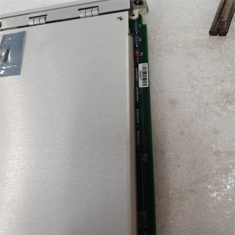
产品实拍图Product picture
模拟范围
电流
范围
时间
G型 0~100.0%0.0~30.0
P型 0~80.0%0.0~30.0
输出
频率
输出
电压
(有效
价值)
制动
能量
直流注入
制动时间
跑步
命令
时间
时间
图5-13启动模式1
F2.05 Acc/Dec模式范围:0.1.2【0】
0:线性Acc/Dec模式
输出频率根据
恒定速率,如图5-14所示。
1: S坡道Acc/Dec
输出频率根据
S形曲线,如图5-15所示。
2: 带限流功能的Acc/Dec模式
驱动器可以保持其输出电流低于
自动限流阈值(见FL.07),以及
根据负载完成Acc或Dec过程
条件
频率
时间
fmax
T1和T2
图5-14线性Acc/Dec
1.
2.
3.
3.
2.
1.
t1和t2
fmax
频率
时间
图5-15 S-ramp Acc/Dec
注:
在自动Acc/Dec模式下,F0.10、F0.11和
F3.17~F3.22无效。
F2.06 S斜坡范围的起始时间:10~50%【20.0%】
F2.07 S斜坡范围的上升时间:10~80%【60.0%】
F2.06和F2.07仅在Acc/Dec
模式为S斜坡Acc/Dec模式(F2.05=1),以及
F2.06+F2.07≤90%.
S形曲线的启动过程如图5-15所示
as”①” , 式中:输出频率的变化率
从0增加;
S形曲线上升过程如图5-15所示
as”②”, 其中,输出频率的变化率为:
常数
S形曲线的结束过程如图5-15所示
as”③”, 式中:输出频率的变化率
减小到0;
S-ramp Acc/Dec模式适用于输送负荷
例如电梯和输送带。
F2.08停止模式范围:0.1.2【0】
0:12月停止
收到停止命令后,驱动器减小
根据Dec时间确定其输出频率,以及
当频率降至0时停止。
1: 停下来
收到停止命令后,驱动器停止
立即输出功率,电机停止在
机械惯性的影响。
第5章参数介绍49
EV2000系列通用变速驱动用户手册
2: Dec停止+直流注入制动
收到停止命令后,驱动器减小
其输出频率根据Dec时间和启动
输出频率达到时的直流注入制动
制动过程的初始频率。
请参阅F2.09~F2.12的介绍
直流注入制动的功能。
F2.09直流注入制动
停止时的初始频率
范围:0.00~60.00Hz
【0.00Hz】
F2.10直流注入制动
车站等候时间
范围:0.00~10.00s
【0.00s】
F2.11直流注入制动
停止电流
范围:取决于
驱动器型号【0.0%】
F2.12直流注入制动
停车时间
范围:取决于
驱动器型号【0.0s】
停止时直流注入制动等待时间:持续时间
从工作频率达到直流时开始
喷射制动初始频率(F2.09)到时间
当施加直流注入制动时。
驱动器在等待时间内没有输出。通过
设置等待时间,初始电流过冲
当驱动器驱动a时,可以减少制动阶段
大功率电机。
直流注入制动电流和时间的范围为:
根据驱动器的型号,见表5-2。
停止时的直流注入制动电流为
驱动器的额定电流。没有直流注入制动
当制动时间为0.0s时。
表5-2直流注入制动功能
模型制动
停止电流
制动时间
停止
G型 0~100.0%0.0~30.0
P型 0~80.0%0.0~30.0
输出频率。
制动初始频率
输出
伏特
(均方根值)
制动
能量
制动时间
操作
命令
等待时间
图5-16 Dec至停止+直流注入制动
注:
停止时的直流注入制动电流(F2.11)为***比
驱动器的额定电流值。
F2.13动态制动范围:0,1【0】
0:禁用动态制动
1: 启用动态制动
注:
必须根据实际情况正确设置此参数
条件,否则控制性能可能为
影响
F2.14制动工作时间比
驱动器总工作时间套件
范围:0.0~
100.0%【2.0%】
此功能对于内置制动的驱动器有效
电阻。
注:
必须测量制动电阻的电阻和功率
在设置该参数时考虑。
5.4辅助运行参数
(F3组)
F3.00反反转运行功能范围:0.1【0】
0:禁用
1: 启用
注:
该功能在所有控制模式下都有效。
F3.01运行延迟时间
后退/前进范围:0~3600s【0.0s】
延迟时间是零频率下的过渡时间
当驱动器切换其运行方向时,如图所示
在图5-17中为t1。
时间
t1
输出
频率
图5-17从
Model The range
of current
The range of
time
G型 0~100.0% 0.0~30.0s
P型 0~80.0% 0.0~30.0s
Output
frequency
Output
voltage
(effective
value)
Braking
energy
DC injection
braking time
Running
command
Time
Time
Fig. 5-13 Starting mode 1
F2.05 Acc/Dec mode Range:0. 1. 2【0】
0: Linear Acc/Dec mode
Output frequency increases or decreases according to a
constant rate, as shown in Fig. 5-14.
1: S ramp Acc/Dec
Output frequency increases or decreases according to a
S-shape curve, as shown in Fig. 5-15.
2: Acc/Dec mode with current limiting function
The drive can maintain its output current below the
current limiting threshold (see FL.07) automatically and
complete the Acc or Dec process according to the load
condition.
Frequency
Time
fmax
t 1 t 2
Fig. 5-14 Linear Acc/Dec
1
2
3
3
2
1
t1 t2
fmax
Frequency
Time
Fig. 5-15 S-ramp Acc/Dec
Note:
In auto Acc/Dec mode, settings of F0.10, F0.11 and
F3.17~F3.22 are invalid.
F2.06 Starting time of S ramp Range:10~50%【20.0%】
F2.07 Rising time of S ramp Range:10~80%【60.0%】
F2.06 and F2.07 are only active when the Acc/Dec
mode is S-ramp Acc/Dec mode(F2.05=1), and
F2.06+F2.07≤90%.
Starting process of S-shape curve is shown in Fig. 5-15
as “①” , where the change rate of output frequency
increases from 0;
Rising process of S-shape curve is shown in Fig. 5-15
as “②”, where the output frequency’s changing rate is
constant;
Ending process of S-shape curve is shown in Fig. 5-15
as “③”, where the changing rate of output frequency
decreases to 0;
S-ramp Acc/Dec mode is suitable for the conveying load
such as elevator and conveying belt.
F2.08 Stopping mode Range:0. 1. 2【0】
0: Dec-to-stop
After receiving the stopping command, the drive reduces
its output frequency according to the Dec time, and
stops when the frequency decreases to 0.
1: Coast-to-stop
After receiving the stopping command, the drive stops
outputting power immediately and the motor stops under
the effects of mechanical inertia.
Chapter 5 Parameter Introductions 49
EV2000 Series Universal Variable Speed Drive User Manual
2: Dec-to-stop+DC injection braking
After receiving the STOP command, the drive reduces
its output frequency according to the Dec time and starts
DC injection braking when its output frequency reaches
the initial frequency of braking process.
Refer to the introductions of F2.09~F2.12 for the
functions of DC injection braking.
F2.09 DC injection braking
initial frequency at stop
Range:0.00~60.00Hz
【0.00Hz】
F2.10 DC injection braking
waiting time at stop
Range:0.00~10.00s
【0.00s】
F2.11 DC injection braking
current at stop
Range: dependent on
drive’s model【0.0%】
F2.12 DC injection braking
time at stop
Range: dependent on
drive’s model【0.0s】
DC injection braking waiting time at stop: The duration
from the time when operating frequency reaches the DC
injection braking initial frequency(F2.09) to the time
when the DC injection braking is applied.
The drive has no output during the waiting time. By
setting waiting time, the current overshoot in the initial
stage of braking can be reduced when the drive drives a
high power motor.
The range of DC injection braking current and time are
dependent on drive’s model, see Table 5-2.
DC injection braking current at stop is a percentage of
drive’s rated current. There is no DC injection braking
when the braking time is 0.0s.
Table 5-2 DC injection braking function
Model Braking
current at stop
Braking time
at stop
G型 0~100.0% 0.0~30.0s
P型 0~80.0% 0.0~30.0s
Output Freq.
Initial Freq.of braking
Output
volt
(RMS value)
Braking
Energy
Braking time
Operating
command
Waiting time
Fig. 5-16 Dec-to-stop + DC injection braking
Note:
DC injection braking current at stop(F2.11) is a percentage
value of drive’s rated current.
F2.13 Dynamic braking Range:0,1【0】
0: Dynamic braking is disabled
1: Dynamic braking is enabled
Note:
This parameter must be set correctly according to the actual
conditions, otherwise the control performance may be
affected.
F2.14 Ratio of working time of braking
kit to drive’s total working time
Range:0.0~
100.0%【2.0%】
This function is effective for the drive with built-in braking
resistor.
Note:
Resistance and power of the braking resistor must be taken
into consideration when setting this parameters.
5.4 Auxiliary Operating Parameters
(Group F3)
F3.00 Anti-reverse running function Range:0. 1【0】
0: disabled
1: enabled
Note:
This function is effective in all control modes.
F3.01 Delay time of run
reverse/forward Range:0~3600s【0.0s】
The delay time is the transition time at zero frequency
when the drive switching its running direction as shown
in Fig. 5-17 as t1.
Time
t 1
Output
frequency
Fig. 5-17 Delay time from