产品介绍Product introduction

产品信息产品类别:模块卡件
品牌:DCS、PLC
电话:15270269218
联系人:叶经理
质保期:1年
加工定制:不可定制
产地/厂家:美国
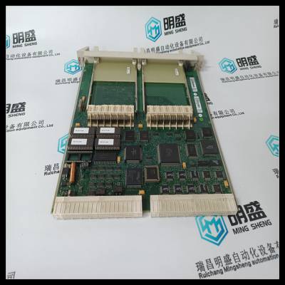
产品实拍图Product picture
CI852由处理器单元通过CEX总线供电,因此需要:
无需额外的外部电源。FF H1总线上的现场设备未通电
从CI852。
连接到CI852的AC 800M控制器构成基础
现场总线连接设备。
使用以下步骤安装CI852/TP852:
1.将装置安装到DIN导轨上,请参见将AC 800M装置安装在DIN导轨上
在第65页,将PM86x/TP830处理器单元安装在单个
配置见第78页。
2.在基金会现场总线H1电缆上安装连接器。连接
将屏幕连接到连接器内的接地端子,以使屏幕接地
通过CI582。
3.将基金会现场总线H1电缆连接至底板上的触点。
基金会现场总线H1连接
将FF H1总线连接到位于TP852基板上的阳DB9连接器。
基金会现场总线使用屏蔽双绞线是:
推荐(见附录C,推荐组件)。
表13.CI852和TP852基金会现场总线H1连接器
引脚名称描述
1–5–未使用
6 FB-P接收/发送数据线,正极性
7 FB-N接收/发送数据线,负极性
8–9–未使用
安装基金会现场总线H1接口,CI852/TP852第2节安装
114 3BSE036351-510 A
有关设计现场总线(连接器、电缆和设备)的更多信息,
参见现场总线文档。
参考供应商、设备、服务和其他现场总线相关项目的目录为
可通过互联网网站在线访问现场总线。
为现场设备供电
需要现场总线供电的现场设备需要特殊电源
连接到数据线(与现场设备相同)。为避免现场总线信号短路,仅使用具有阻抗的电源
专为基金会现场总线设计的特征。
请勿为此目的使用SD82x电源装置。
请注意,CI852机组没有机组冗余。
不能在高完整性控制器中使用。
CI852已被CI860通信接口取代。CI852仅为
由于遗留原因而描述。
不可能通过热插拔更换CI852单元,也不允许:
在包含CI852的系统中执行固件的在线升级。
第2节安装安装RS-232C接口,CI853/TP853
3BSE036351-510 A 115
安装RS-232C接口,CI853/TP853
CI853由处理器单元通过CEX总线供电,因此不需要
额外的外部电源。
使用以下步骤安装CI853/TP853:
1.将装置安装到DIN导轨上,请参见将AC 800M装置安装在DIN导轨上
在第65页,将PM86x/TP830处理器单元安装在单个
配置见第78页。
2.将电缆(15米(16.4码))连接到
底板。将电缆屏蔽连接到接头内的接地端子
通过CI583将屏幕接地。
3.如果需要长度超过15米(16.4码)的电缆,则使用短距离调制解调器
必须使用TC562。在这种情况下,将调制解调器安装到DIN导轨上
在合适的位置,将24 V直流电源连接到调制解调器并连接
从CI853到TC562调制解调器输入端子的电缆TK853
4.将TC562调制解调器输出端子连接到输出电缆。
TC562调制解调器可用于以下距离/速度:
•传输速度为19200位/秒,可达1000米(1100码)
•高达12000米(13100码),传输速度为1200位/秒
连接器
将RS-232C通道连接到标有COM1和COM2的RJ45连接器
在TP853基板上。
表14.CI853 RS23-C接口——COM1和COM2连接器
引脚名称方向说明
1–9–见TP830上的COM3,第85页的表6。
请注意,CI853机组没有机组冗余。
安装PROFIBUS DP接口,CI854/
CI852 is powered from the processor unit via the CEX-Bus and requires therefore
no additional external power source. No field device on the FF H1 bus is powered
from the CI852.
An AC 800M Controller connected to a CI852 constitutes a FOUNDATION
Fieldbus linking device.
Use the following procedure to install the CI852/TP852:
1. Mount the unit onto the DIN-rail, see Mounting AC 800M Units onto DIN-Rail
on page 65 and Installing the PM86x/TP830 Processor Unit in Single
Configuration on page 78.
2. Install a connector on the FOUNDATION Fieldbus H1 cable. Connect the
cable screen to the ground terminal within the connector to ground the screen
via CI582.
3. Connect the FOUNDATION Fieldbus H1 cable to the contact on the baseplate.
FOUNDATION Fieldbus H1 Connection
Connect the FF H1 bus to the male DB9 connector located on the TP852 Baseplate.
The use of shielded twisted pair cables for FOUNDATION Fieldbus is
recommended (see Appendix C, Recommended Components).
Table 13. CI852 and TP852 FOUNDATION Fieldbus H1 Connector
Pin Designation Description
1–5 – Not used
6 FB-P Receive/transmit data line, positive polarity
7 FB-N Receive/transmit data line, negative polarity
8–9 – Not used
Installing the FOUNDATION Fieldbus H1 Interface, CI852/TP852 Section 2 Installation
114 3BSE036351-510 A
For additional information on designing a fieldbus (connectors, cables and devices),
see fieldbus documentation.
A catalog referencing suppliers, devices, services and other fieldbus-related items, is
available for FIELDBUS ONLINE via the Internet web site.
Powering Field Devices
Field devices requiring power from the fieldbus need special power supplies
connected to the data wires (in the same way as a field device). To avoid shortcircuiting of fieldbus signals, use only power supplies with impedance
characteristics specifically designed for FOUNDATION Fieldbus.
Do not use SD82x power supply units for this purpose.
Note that there is no unit redundancy for the CI852 unit.
Cannot be used in High Integrity Controller.
CI852 has been replaced by the CI860 communication interface. CI852 is only
described for legacy reasons.
It is not possible to change the CI852 unit via hot swap and it is not allowed to
perform an online upgrade of firmware in a system containing CI852.
Section 2 Installation Installing the RS-232C Interface, CI853/TP853
3BSE036351-510 A 115
Installing the RS-232C Interface, CI853/TP853
CI853 is powered from the processor unit via the CEX bus and requires therefore no
additional external power source.
Use the following procedure to install the CI853/TP853:
1. Mount the unit onto the DIN-rail, see Mounting AC 800M Units onto DIN-Rail
on page 65 and Installing the PM86x/TP830 Processor Unit in Single
Configuration on page 78.
2. Connect the cable (maximum 15 m (16.4 yd)) to one of the contacts on the
baseplate. Connect the cable screen to the ground terminal within the connector
to ground the screen via CI583.
3. If cables longer than 15 m (16.4 yd.) are required, then a short distance modem
TC562 must be used. In this case mount the modem onto a DIN-rail in a
suitable position, connect a 24 V DC power supply to the modem and connect
cable TK853 from CI853 to the TC562 modem input terminals
4. Connect the TC562 modem output terminals to the outgoing cable.
The TC562 modem can be used for the following distances/speeds:
• Up to 1000 m (1100 yd) with transmission speed 19200 bit/s
• Up to 12000 m (13100 yd) with transmission speed 1200 bit/s
Connectors
Connect the RS-232C channels to the RJ45 connectors marked COM1 and COM2
on the TP853 Baseplate.
Table 14. CI853 RS23-C Interface – COM1 and COM2 Connectors
Pin Designation Direction Description
1–9 – – See COM3 on TP830, Table 6 on page 85.
Note that there is no unit redundancy for the CI853 unit.
Installing the PROFIBUS DP Interface, CI854/
 DSQC345B工控继电模块PLC库存
¥6973.00
 DSQC345C工控继电模块PLC库存
¥6973.00
 DSQC345D工控继电模块PLC库存
¥6973.00
 DSQC345E工控继电模块PLC库存
¥6973.00
 DSQC346工控继电模块PLC库存
¥6973.00
 DSQC346B工控继电模块PLC库存
¥6973.00


