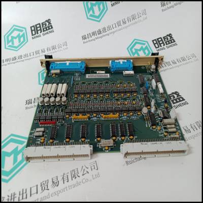
 S71262-NANANA 模块用于控制传输速度 Kollmorgen
¥3137.00
 U0213-0006-001-11 BLIII-D 服驱动器 OKUMA
¥3137.00
 S71262-NANANA 模块用于控制传输速度 Kollmorgen
¥3137.00
 U0213-0006-001-11 BLIII-D 服驱动器 OKUMA
¥3137.00
UKC-5125-5X4A A2R13903-06 01 伺服电力控制编码器 FLOWSERVE
UKC-5125-5X4A A2R13903-06 01 伺服电力控制编码器 FLOWSERVE
o区。如果变化很小,这将不是问题;
如果较大,可能需要在某些区域提供补充加热
房间或区域。表中的热损失是设计时的总热损失
条件,但不考虑发生的内部热增益
当房间被占用时。由于所有这些因素
“加热温差”没有实际意义,除非
早上6点左右无人居住的大楼。
此讨论有助于解释为什么某些建筑系统具有
很难让房客满意。业主的压力或设计师的经验不足通常会导致大面积控制区的荷载变化
由于占用、使用或暴露而跨越区域。这***
随后的不满和不同的个人舒适期望加剧了问题。
摘要中的每平方英尺CFM表格非常有用
检查手动和计算机计算的项目。以下数值
占用空间中约0.7%是可疑的,通常会导致:
通风率不足,并抱怨“闷”和高
湿度对于VAV,最小设计速率应约为0.75至1.0
(ft3/min)/ft2
,这将导致建筑物平均实际循环
速率为0.5至0.6(ft3/min)/ft2
.高于3.0(ft3/min)/ft2的值可以创建
分布问题,高速气流作用在乘客身上。如果
重新检查计算表明,这些高气流是必要的,因此应特别注意空气分配技术。洁净室和大型计算机室通常需要气流
8至10(ft3/min)/ft2的速率
.处理方法见第5章
这些是利率。
经验表明,小幅调整后的高利率下降
高达3.0和低至0.75(ft3/min)/ft2的速率将导致较少的问题
而不是使用计算的速率。同样,判断和常识
需要。
上述评论意味着系统概念必须先于
计算。也就是说,在进行总结之前,必须至少对要使用的HVAC系统类型、分区、设备位置和控制策略进行近似。虽然这不是一个abDesign程序:***部分
下载自数字工程图书馆@McGraw-Hill()
版权所有©2004麦格劳-希尔公司。版权所有。
任何使用均受网站上给出的使用条款的约束。
设计程序:***部分77
溶质要求,这将使计算过程更加高效。
概念应灵活,以适应所需的变化
由于不可预见的并发症和***一分钟的使用变更
以及占用某些建筑空间。
此注释扩展到管网的尺寸。多年后
从经验来看,似乎谨慎的做法是偏大一点,
而不是有点太小。
3.7动态与静态
负荷计算
所有手动负荷计算和许多计算机程序都假设存在静态或稳态条件。但是稳态
空调情况下不存在条件。如果暖通空调
如果系统和控制功能正常,则室内环境将略有变化。然而,内部和外部
负载不断变化。冷负荷系数的函数
计算中的(CLF)是近似这些瞬态的影响
使静荷载计算产生更类似结果的因素
“真实”动态负载。
导致这些因素的研究源于广泛的
公认的条件是,旧的计算方法总是导致
暖通空调系统和设备尺寸过大。能量的增加
在20世纪70年代,设备成本导致广泛接受
新方法,因为一般来说,如果设备尺寸过大,总体运行效率会降低。即使如此,表中的因素
是保守的,有些尺寸过大将成为常态
UKC-5125-5X4A A2R13903-06 01 伺服电力控制编码器 FLOWSERVE
UKC-5125-5X4A A2R13903-06 01 伺服电力控制编码器 FLOWSERVE
o zone. If the variation is small, this will not be a problem;
if large, it may be necessary to provide supplemental heating in some
rooms or zones. The tabulated heat loss is a gross heat loss at design
conditions, but with no credit for the internal heat gains which occur
when the room is occupied. Because of all these factors, the tabulated
‘‘heating temperature difference’’ is not really meaningful except in an
unoccupied building at about 6 a.m.
This discussion helps explain why some building systems have a
hard time satisfying the tenants. Owner pressure, or designer inexperience, often results in large area control zones with loads that vary
across the zone due to occupancy, use, or exposure. This guarantees
subsequent dissatisfaction, and different personal comfort expectations exacerbates the problem.
The CFM per square foot tabulation in the summary is a very useful
check item for both manual and computer calculations. Values below
about 0.7 in an occupied space are suspect and will usually result in
inadequate ventilation rates with complaints of ‘‘stuffiness’’ and high
humidity. For VAV a minimum design rate should be about 0.75 to 1.0
(ft3 /min)/ ft2
, which will result in a building average actual circulation
rate of 0.5 to 0.6 (ft3 /min)/ ft2
. Values above 3.0 (ft3 /min)/ ft2 can create
distribution problems, with high-velocity drafts on the occupants. If a
recheck of the calculations shows that these high airflows are necessary, then special attention should be paid to the air distribution technique. Clean rooms and large computer rooms typically need airflow
rates of 8 to 10 (ft3 /min)/ ft2
. See Chap. 5 for methods of dealing with
these rates.
Experience has shown that small adjustments of high rates down
to 3.0 and low rates up to 0.75 (ft3 /min)/ ft2 will cause fewer problems
than using the calculated rates. Again, judgment and common sense
are needed.
The above comments imply that the system concept must precede
the calculations. That is, the types of HVAC systems to be used, zoning, location of equipment, and control strategies must be at least approximated before the summaries are made. While this is not an abDesign Procedures: Part 1
Downloaded from Digital Engineering Library @ McGraw-Hill ()
Copyright © 2004 The McGraw-Hill Companies. All rights reserved.
Any use is subject to the Terms of Use as given at the website.
Design Procedures: Part 1 77
solute requirement, it will make the calculation process more efficient.
The concept should be flexible, so as to accommodate changes required
by unforeseen complications and last-minute alterations in the use
and occupancy of certain building spaces.
This comment extends to the sizing of ductwork. After many years
of experience, it seems prudent to err on the side of a little too large,
rather than a little too small.
3.7 Dynamic versus Static
Load Calculations
All manual load calculations and many of the computer programs assume that a static or steady-state condition exists. But steady-state
conditions do not exist in an air conditioning situation. If the HVAC
systems and controls are functioning properly, then the indoor environment will vary only slightly. However, the internal and external
loads are constantly changing. The function of the cooling load factor
(CLF) in the calculation is to approximate the effect of these transient
factors so that the static load calculation will yield results more like
the ‘‘real’’ dynamic load.
The research which led to these factors resulted from the widely
recognized condition that older calculation methods invariably led to
oversizing of HVAC systems and equipment. The increases in energy
and equipment costs during the 1970s led to a broad acceptance of the
new methods because, in general, overall operating efficiency decreases if equipment is oversized. Even so, the factors in the tables
are conservative, and some oversizing will norm
 在线问
在线问
