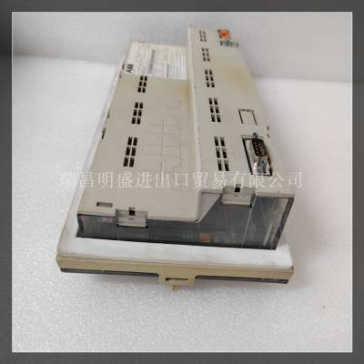
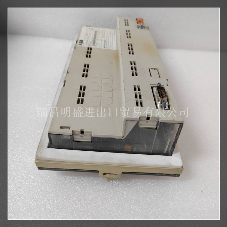
产品标题:REF542PLUS?1VCR007346控制板卡说明书文档
型号:REF542PLUS?1VCR007346
质保:七天验收期,质保期一年
品牌:ABB
产品图片展示

产品详情资料:
SCXI-1340有一个额外的公接头,用于SCXI-1180馈通面板或需要直接连接到MIO板的附加模块或电路板。SCXI-1340后面板提供机械和电气屏蔽。表E-1列出了MIO板和SCXI-1100的引脚等效物。请执行以下步骤安装SCXI-1340:1.确保计算机和SCXI机箱已关闭。2.在机箱中安装SCXI模块。3.将安装支架连接器插到模块后信号连接器上(见图E-1)。确保支架上的对齐卡舌进入机箱的上板导轨。4.将安装支架拧到机箱后部的螺纹条上。5.将电缆组件的松动端连接到MIO板I/O连接器。检查安装情况。在步骤1之后,这些步骤的顺序并不重要;然而,在机箱中安装模块后,更容易找到安装支架的正确位置。如果要将电缆连接到断接连接器,如果在安装SCXI-1340之前连接***根电缆,则安装最容易。
产品英文详情资料:
The SCXI-1340 has an extra male breakout connector for use with the SCXI-1180 feedthrough panel or additional modules or breadboards that need a direct connection to the MIO board.The SCXI-1340 rear panel gives both mechanical and electrical shielding. Table E-1 lists the pin equivalences of the MIO board and the SCXI-1100.Perform the following steps to install the SCXI-1340: 1. Make sure that the computer and the SCXI chassis are turned off. 2. Install the SCXI module in the chassis. 3. Plug the mounting bracket connector onto the module rear signal connector (see Figure E-1). Make sure the alignment tab on the bracket enters the upper board guide of the chassis. 4. Screw the mounting bracket to the threaded strips in the rear of the chassis. 5. Connect the loose end of the cable assembly to the MIO board I/O connector. Check the installation.After step 1, the order of these steps is not critical; however, it is easier to locate the correct position for the mounting bracket with a module installed in the chassis. If you are attaching a cable to the breakout connector, installation is easiest if you attach the second cable before installing the SCXI-1340.