- 是加工定制
- 爱莎品牌
- 否是否跨境货源
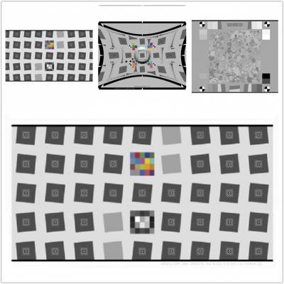
测试卡展示
测试卡说明
亮度-色度偏移(Y-C-Offset)描述亮度和色度通道之间的时间差。时间差必须在辉度的50%幅度点和色度转换点之间测量。两个信号mus来自相同的测试模式。
Luminance-Chrominance-Offset (Y-C-Offset) describes the temporal difference between the luminance and chrominance channel. The temporal difference has to be measured between points of 50 percent amplitude of luminance and chrominance transition. Both signals mus come from the same test pattern.
Measuring procedure for PAL / NATSC
The measurement setup has to be on a par with figure 2 below.

The test chart consists of a green cross on gray background (20% transparency). The luminance signal E'Y and the chrominance signals R'(R-Y) and R'(B-Y) are generated with a calibrated demodulator. With the aid of a two-beam-oscilloscope the time difference is measured. The Y-C-Offset of the demodulator has to be measured and specified with the results.
Horizontal Y/C-Offset
Line M has to be selected (see figure 2, 2a, 2b) and, shown in figures 2d and 2e, displayed increased on the scope. The time difference tdH in ns has to be measured between the 50% points of level. When reading out the luminance signal Y and the chrominance signal C separately, the measurement of this signals has to be realized without demodulation of the chrominance signal (see figure 2m, 2n, 2p, 2r, 2s). This method only applies to PAL and NTSC. The rise time t1 and the fall time t2 of the chrominance signals E'(R-Y) and E'(B-Y) must be measured (see figure 2f).
Vertical Y/C-Offset
With the aid of the scope a half picture is chosen (see figure 2d and 2e) and displayed increased (see figure 2k and 2l). The time difference tdv between the 50% points of the luminance signal E'Y and the chrominance signals E'(R-Y) and E'(B-Y) has to be measured and shown in picture line periods (see figure 2k and 2l).
Presentation of results
Time difference, rise edge and fall edge have to be described with luminace edge for reference in the following modality:
horizontal offset tdH in ns (figures 2d and 2e)
vertical offset tdv in TV lines (figures 2k and 2l)
chrominance rise edge t1 in ns (figure 2f)
chrominance fall edge t2 in ns (figure 2f)
Y/C-Offset of the demodulator in ns (figure 2f)
Note:
Due to the small bandwith of the chrominace channel, the rise edge of the chrominance signal is generated before the rise edge of the luminance signal (negative offset) and the fall edge after the fall edge of the luminance signal (positive offset). The time difference between both is taken for main offset, which can be positive or negative.
 在线问
在线问
- 是
- 爱莎
- 否


